48
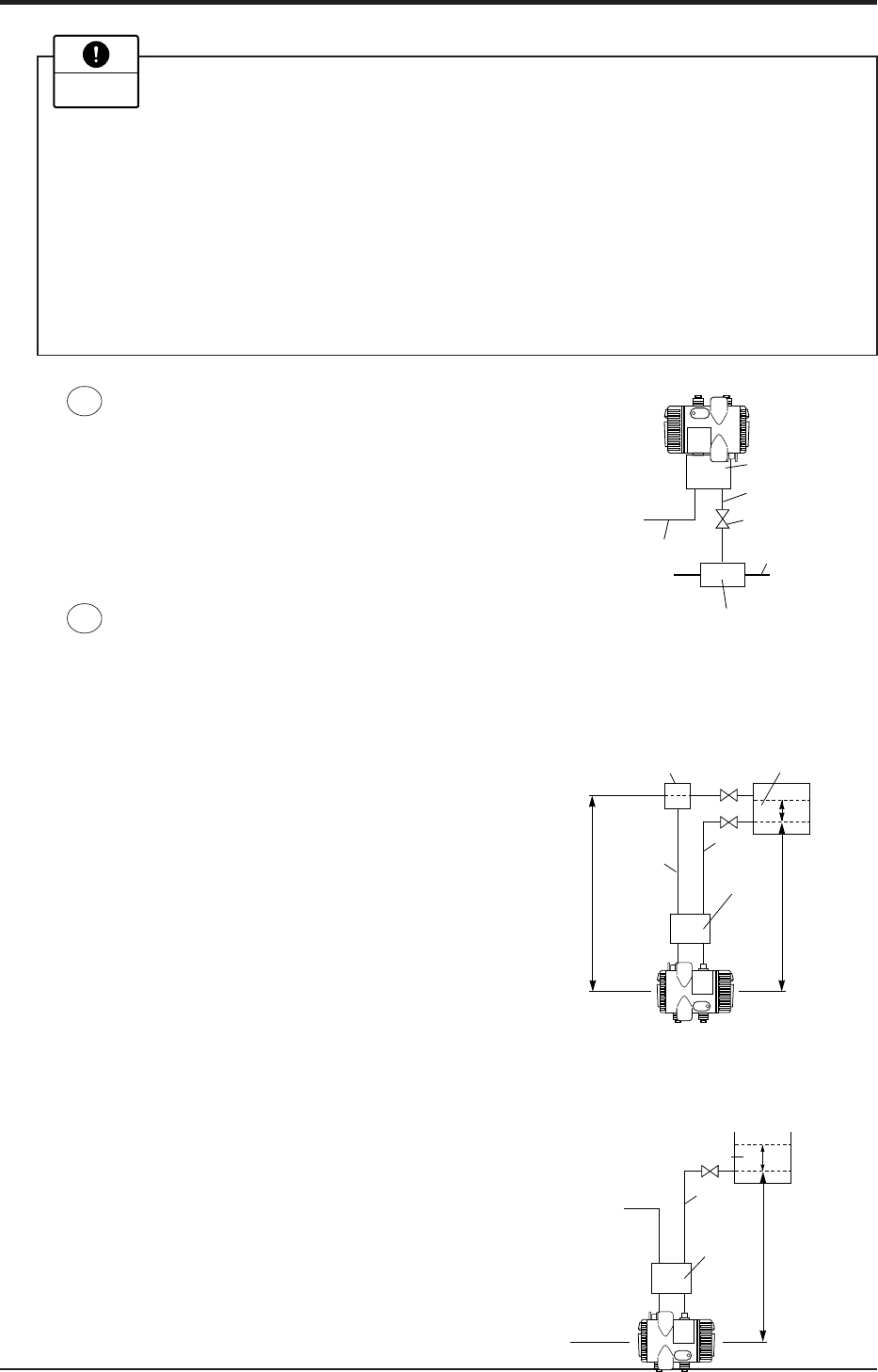
Pressure measurement (in case of gas)
Mount the transmitter above the process pipes to
preventing moisture from entering the inside of
transmitter.
Level measurement
(1) In case of wet leg:
For measurement, connect the highest liquid level tapping of tank with the low pres-
sure side of transmitter, and the lowest liquid level tapping of tank with the high
pressure side of transmitter.
< Level calculation formula >
LRV: rH
2
- r
0
H
1
URV: rH
2
+ r
1
h - r
0
H
1
Span (DP): r
1
h
LRV: Low limit of measurement (0% point)
URV: High limit of measurement (100% point)
r
0
,r,r
1
: Density
H
1
, H
2
: Liquid level, h: Liquid level change
(2) In case of dry leg:
For an open tank, leave the low pressure side of transmitter open to atmosphere.
< Level calculation formula >
LRV: rH
1
URV: rH
1
+ r
1
h
Span (DP): r
1
h
LRV: Low limit of measurement (0% point)
URV: High limit of measurement (100% point)
r,r
1
: Density
H
1
: Liquid level, h: Liquid level change
Stop valve
Process pipe
Pressure source
Manifold valve
Impulse pipe
Atmospheric
air inlet
H
1
H
2
Max. liquid
level
Min. liquid
level
Condensor
ρ
0
ρ
Manifold
valve
High
pressure
side
Low
pressure
side
h
ρ
1
H
1
Max. liquid
level
Min. liquid
level
Manifold
valve
High
pressure
side
Low
pressure
side
Atomospheric
air inlet
h
ρ
1
ρ
5
6
(1) Protection is required to prevent dust from entering through the atmospheric
air inlet after installation of the manifold valve.
(2) If process pressure range is narrow (below 10kPa (1000mmH
2
O)), the follow-
ing should be considered.
• Pressure variation due to wind around atmospheric air inlet
• Temperature variation near process taps
• Difference in atmospheric pressure between process tap and transmitter
location.
To overcome this, provide atmospheric pressure-side pipe with a proper orifice
and consider accommodating the transmitter and atmospheric air inlet in a box.
Important
