5
1. After adjustment of the transmitter, it should be kept energized for about 10
seconds to write the adjustment result into memory.
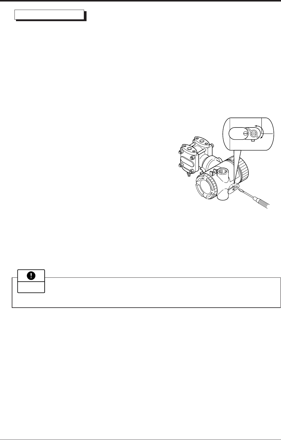
2. Use a blade-edge screwdriver for adjusting the zero/span adjustment screw.
Important
Decrease
Increase
When all the checks and preparatory operations are finished, tighten the cover securely. (Tighten-
ing torque 20 N•m {2 kgf•m} <14ft-lb>)
Zero point check
Turn on the power to the transmitter.
Check the output signal of the transmitter by connecting a DC ammeter across CK+ and CK– of
the terminal block.
After ten minutes or longer, adjust the transmitter output current to 4 mA (zero adjustment). (See
below.)
(1) Zero adjustment
Zero point of the transmitter is adjustable by the zero screw on the electronics housing with
the zero adjustment screw.
• If the transmitter is locked (see section
“Operating procedure”, Lock of adjustment
function), it is not possible to adjust with the
external adjustment screw.
• When a digital indicator is attached to the
transmitter, make sure that the LCD lamp
“ZERO” is ON.
(2) Adjustment by HHC
Refer “zero adjustment” explained in section 7.1.


