32
2.Selection of transmitter adjustment method
LOCAL/COMM. Changing switch decides the method of FCX-CII transmitter adjustment. If switch
is set to “COMM.” side, adjustment of transmitter is carried out by HHC. This method is explained
in instruction manual.
If switch is set to “LOCAL” side, adjustment of transmitter is carried out by Mode setting switch
and Damping setting switch.
This method is explain below.
3.Range change procedure
For changing the measuring range, carry out zero adjustment first, and span adjustment next. (If
zero adjustment is performed after span adjustment, the 100% point may not be adjusted correctly.).
There is no interference between zero adjustment and span adjustment.
3.1 Zero adjustment(Change Lower Range Value)
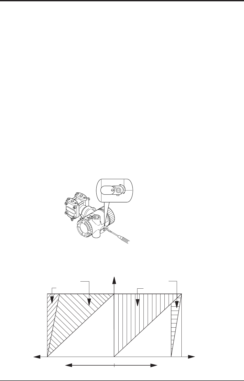
Zero point of the transmitter is adjustable by the external adj. screw with the mode setting
switch set at “0” position.
(1) Check if “ZERO” is lit on the LCD indicator.
If not lit, set the mode setting switch to “0” position.
(2) Apply standard input pressure corresponding to new Lower Range Value
(3) Adjust output signal to 4.00mA by turning the external adj. screw
Decrease
Increase
For zero suppression or elevation ranges, apply the specified LRV pressure in advance and adjust
the output signal to 4.00mA using the external adj. screw.
max span
min span
Max Zero suppression with :
Output
signal
100% (20mA)
Input signal
%URL
+100%
-100%
Max zero elevation with :
0%
Zero elevation
Zero suppression
max span
min span
0%
(4mA)


