35
5.2 Troubleshooting
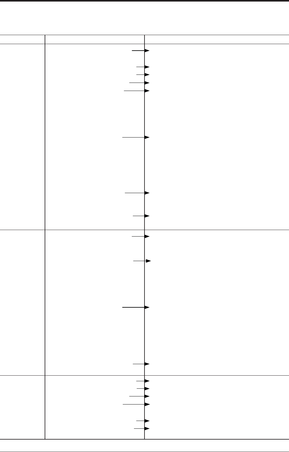
If an abnormality occurred in the process or transmitter, action should be taken with reference to the
table below.
If remedy is impossible, contact Fuji Electric’s service department.
(1) The manifold valve does
not open/close normally.
(2) Pressure leak is occurring.
(3) Process piping is improper.
(4) Process pipe is clogged.
(5) Power supply voltage
and/or load resistance is
improper.
(6) Voltage between the
external connection
terminals of transmission
unit is wrong.
(7) Zero and span are not
adjusted.
(8) Electronics unit is faulty.
(1) Same as (1) to (4) above
(2) Power supply polarity is
wrong.
(3) Power supply voltage and/
or load resistance is
improper.
(4) Voltage between the
external connection
terminals is wrong.
(5) Electronics unit is faulty.
(1) Process piping is improper.
(2) Gas or solution is mixed in.
(3) Liquid density changes.
(4) Ambient temperature
changes widely.
(5) Zero or span has deviated.
(6) Electronics unit is faulty.
Repair the valve so that it opens/closes normally.
Repair a leak.
Make correct piping.
Eliminate the cause of clogging.
Make arrangement to obtain proper values.
(For power supply voltage and load resistance,
refer to “7.2” (page 50).)
(For intrinsically safe installations, the power
supply voltage should be 10.5 to 26V DC for
smart type.)
Check for faulty cable, insulation, etc. and repair
as needed.
(For power supply voltage and load resistance,
refer to “7.2” (page 50).)
(For intrinsically safe installations, the power
supply voltage should be 10.5 to 26V DC for
smart type.)
Readjust according to sections 4 (page 9).
Replace the electronics unit according to 5.3 (page
32).
Correct wiring (according to 7.1 (page 48)).
Make arrangement to obtain proper values.
(For power supply voltage and load resistance,
refer to “7.2” (page 50).)
(For intrinsically safe installations, the power
supply voltage should be 10.5 to 26V DC for
smart type.)
Check for faulty cable, insulation, etc. and repair
as needed.
(For power supply voltage and load resistance,
refer to "7.2" (page 50).)
(For intrinsically safe installations, the power
supply voltage should be 10.5 to 26V DC for
smart type.)
Replace the electronics unit according to 5.3 (page
32).
Correct the piping.
Vent or drain the transmitter.
Perform density compensation.
Minimize the temperature change.
Readjust zero or span.
Replace the electronics unit according to 5.3 (page
32).
No output
current (less
than 3.8 mA).
Output
current
overshoots
scale
(exceeds
20mA).
Symptom Cause Remedy
Output current
error


