5725A
Instruction Manual
4-22
(ICAL, TP208) with the same amplitude and polarity as the current amplifier input voltage.
The calibration amplifier output is measured by circuitry within the 5700A during
calibration of the 5725A current amplifier. The calibration amplifier output is fed back
to the 5700A Oscillator during ac current operation.
The feedback signal from the precision shunt is applied to both the inner and outer loop
error amplifiers (ISENSE HI, ISENSE LO , pages 1 and 2). The error amplifier section
drives the output stage (TP204) so that the voltage across R272 is one-tenth of the
Current Amplifier input voltage (VINI). Thus, the Current Amplifier is a
transconductance amplifier: output current is proportional to input voltage. This
transconductance is -5A/V.
4-36. Output Stage Section
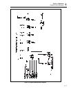
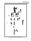
Refer to page 1 of the Current Amplifier schematic. Components U203, R203, R204, and
R209 convert the bipolar ground-referenced output signal from the error amplifier
section into two unipolar supply-referenced waveforms at the inputs to U204A and
U204B. IC U203 also isolates the output stage, which is referenced to a floating common
(ICOM), from the rest of the circuitry, which is referenced to circuit common (VCOM).
The operation of the positive and negative output halves are similar. Only the positive
output section is described below.
In response to a positive polarity error amplifier output (TP204), the current through
R209 increases. This same current flows into pin 2 of U203, causing the voltage drop
across R203 to increase. The voltage across R203 is applied to the positive input of
U204A. U204A drives Q203, Q205, and Q207 until the voltage at the emitter of Q207 is
identical to the voltage at the non-inverting input of U204A. Test point TP204 is a test
input for the output stage when in standby mode. The resulting output stage current can
be monitored at TP208 with a scaling of 200 mV/A.
The quiescent operating point of the output devices is fixed by the bias current of U203
and current source CR205 at about 1A. There is no output stage bias adjustment.
Capacitor C235 and resistors R256 through R260 provide a tertiary feedback path that
guarantees stability when the 5725A is driving the specified inductive loads.
4-37. Monitor Section
Refer to page 1 of the Current Amplifier schematic. Components U211C and D, U210C,
RT203, CR207, and associated resistors and capacitors make up the temperature-
monitoring circuit. Heat sink temperatures above approximately 85°C signal the
ITEMPM fault condition.
Components U207, R280 through 284, and C234 generate a negative voltage at TP207
(DRIVE MONITOR) that remains less than 3.1V in magnitude when the output
compliance voltage is within the linear operating range of the output stage. The output
compliance voltage is not measured by the drive monitor circuit; an overcompliance
condition is inferred from excessive error amplifier output.


