5725A
Instruction Manual
4-12
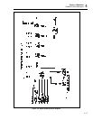
4-16. Power Supply Assembly (A4)
The Power Supply assembly (A4) provides regulated system supplies for all 5725A
assemblies except as noted below, as well as unregulated fan supply and high voltage
supplies for the High Voltage Amplifier. The assembly also includes microprocessor-
controlled switching and an independent current-limit circuit.
Note
Other power supplies are contained on the Current Amplifier assembly
(A2). The A2 assembly includes a high-current supply and a local
±
20V
supply.
The Power Supply assembly has four sections: high voltage supply, switching, current
limit, and system supply section. Each section is first briefly described, then described in
detail.
• High Voltage Supply Section
The high voltage supply section consists of a simple unregulated power supply with
the additional capability of being run at ±400V dc for normal instrument operation,
or at ±50V dc for troubleshooting.
• Switching Section
The switching section behaves like an electronic DPST switch, which by command
of the microprocessor or the current-limit section, shuts down the high voltage
supplies. Microprocessor control alone can turn on the high voltage supplies in
normal operation. At the board level, manual control of the switch is possible to
enable stand-alone turn on of the Power Supply assembly (A4) and the High Voltage
Amplifier assembly (A3).
• Current-Limit Section
The current-limit section shuts down the high voltage supply in a latching mode if
excessive current is drawn by the High Voltage Amplifier or if the ±15V or +5V
supplies fail. This section of the Power Supply assembly consists of a pair of shunts,
a pair of comparators, and a system supply monitor.
• System Supply Section
The system supply section contains various regulated power supplies, and is
comprised of five linear regulators. In addition, the system supply section contains
an unregulated supply for the fan.


