Maintenance
Access Procedures
6
6-13
6-12. Accessing the High Voltage Sense Assembly (A6)
Warning
To avoid electrical shock, do not proceed with the following
access procedure until you have completed the initial access
procedure, which removes line power and checks for high
voltage on the power supply. Line voltage comes directly to
this assembly.
The High Voltage Sense assembly lays flat on the bottom of the instrument, toward the
rear. Proceed as follows to access the High Voltage Sense assembly:
1. Perform the Initial Access Procedure.
2. Follow the Current Amplifier Assembly (A2) access procedure to gain access to the
connectors on the High Voltage Sense Assembly (A6). Remove the connectors and
secure the Current Amplifier Assembly before proceeding.
3. Return the High Voltage Amplifier assembly (and the Current Amplifier assembly if
it has been accessed) to the normal position, and reinstall the assembly retaining
screws.
Note
When reinstalling assemblies, lower them in place squarely to make sure
their connectors seat correctly in the Interconnect assembly connectors.
4. Turn over the 5725A so that the bottom is facing up.
5. Remove the bottom cover by removing the six screws on the bottom surface.
6. Remove the two jack screws from the 5700A subminiature D-connector.
7. Remove the five retaining screws on the High Voltage Sense assembly. Lift the High
Voltage Sense assembly by pulling on the plastic wire-tie loops, and place the
assembly in the service position.
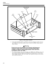
Caution
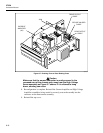
When reinstalling the assembly, refer to Figure 6-6 and make
sure cable harnesses are dressed as shown, to avoid shorting
wires to the bridge rectifier heat sink or chassis.


