Maintenance
Access Procedures
6
6-9
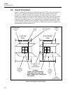
8. Take another DMM reading with the common lead to TP307 and the high lead to
TP304 on the Power Supply assembly. This is the -400V filter capacitor test point,
and it should be at a safe level near zero. This completes the initial access procedure.
6-8. Accessing the Power Supply Assembly (A4)
Warning
To avoid electrical shock, do not proceed with the following
access procedure until you have completed the initial access
procedure, which removes line power and checks for high
voltage on the power supply.
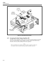
The Power Supply assembly lays flat on the bottom of the instrument, toward the front.
Proceed as follows to access the Power Supply assembly:
1. Perform the Initial Access Procedure.
2. Return the High Voltage Amplifier assembly (A3) (and the Current Amplifier
assembly (A2) if it has been accessed) to the normal position, and reinstall the
assembly retaining screws.
Note
When reinstalling assemblies, lower them in place squarely to make sure
their connectors seat correctly in the Interconnect assembly connectors.
3. Turn over the 5725A so that the bottom is facing up.
4. Remove the five retaining screws on the Power Supply assembly. Lift the Power
Supply assembly by pulling on the plastic wire-tie loops, and place the assembly in
the service position.
Note
When reinstalling the assembly, lower it into place squarely to make sure
its connector seats correctly in the Interconnect assembly connector.
Ensure that both J301 and J303 are properly aligned and connected to
their respective cables.
6-9. Accessing the Digital Assembly (A5)
Warning
To avoid electrical shock, do not proceed with the following
access procedure until you have completed the initial access
procedure, which removes line power and checks for high
voltage on the power supply.
The Digital assembly is oriented vertically just behind the front panel. Proceed as
follows to access the Digital Assembly:
1. Perform the Initial Access Procedure.
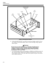
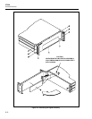
2. Refer to Figure 6-5 for accessing the Digital assembly. Remove the six Allen-head
screws from the sides of the front handles, and remove the three screws from the
front edge of the bottom cover. (You have already removed the top cover in step 1.)
3. The front panel remains connected by the Digital assembly ribbon cable and the
current output cable. Remove the screw in the center of the Digital assembly to free
the pca.


