Installation
Introduction
2
2-3
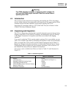
Warning
The 5725A amplifier is capable of supplying lethal voltages. Do
not touch the 5700A output terminals. Read this section before
operating the 5725A.
2-1. Introduction
This section provides instructions for unpacking and installing the 5725A. Procedures
for line voltage selection, fuse replacement, and connection to line power and the 5700A
Calibrator are provided here. Read this section before operating the 5725A.
Instructions for connecting cables to a UUT (Unit Under Test) are in Section 4 of the
5700A/5720A Series II Operator Manual.
2-2. Unpacking and Inspection
The 5725A is shipped in a container that is specially designed to prevent damage during
shipping. Inspect the 5725A carefully for damage, and immediately report any damage
to the shipper. Instructions for inspection and claims are included in the shipping
container.
If you need to reship the 5725A, use the original container. If it is not available, you can
order a new container from Fluke by identifying the amplifier’s model and serial number.
When you unpack the 5725A, check for all the standard equipment listed in Table 2-1.
Report any shortage to the place of purchase or to the nearest Technical Service Center.
If performance tests are required for your acceptance procedures, refer to Section 3 of
the 5700A/5720A Series II Service Manual for instructions.
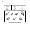
Line power cords available from Fluke are listed in Table 2-2 and illustrated in
Figure 2-1.
Table 2-1. Standard Equipment
Item Model or Part Number
Amplifier 5725A
Line Power Cord (See Table 2-2 and Figure 2-1)
Shielded 5700A/5725A Interface Cable 842901
5725A Getting Started Manual 1780175
5725A CD-ROM (contains Instruction Manual) 1780182
Spare 4A, 250V Fuse 216846
Certificate of Calibration (No Part Number)


