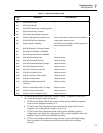
5725A
Instruction Manual
6-14
6-13. Accessing the High Voltage Output Transistors
Warning
During normal operation, the high voltage heat sinks are at
lethal voltage. To avoid electrical shock, do not proceed with
the following access procedure until you have completed the
initial access procedure, which removes line power and checks
for high voltage on the power supply.
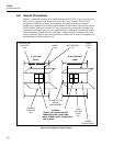
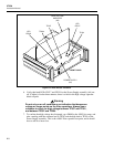
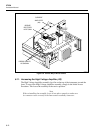
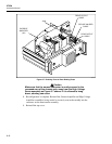
To access the high voltage output transistors (attached to four separate, large heat sinks
in the center of the instrument), proceed as follows:
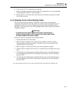
1. Perform the Initial Access Procedure.
2. Disconnect the heat sinks from the High Voltage Amplifier assembly by unplugging
connectors J661, J662, J663, J664. Disconnect the temperature monitor by
unplugging connector J603.
3. Remove the four screws that retain the high voltage heat sink assembly at the bottom
rails.
4. Lift out the heat sink assembly, being careful to keep the cables clear of obstructions
during removal.
5. Each of the four heat sinks is held in place by two screws, one at the top rail and one
at the bottom rail. Labels on each heat sink identify it as P1, P2, N1, or N2. To
remove a heat sink, remove its two retaining screws, and slide it out of the assembly.
6-14. Accessing the Interconnect Assembly (A1)
Warning
To avoid electrical shock, do not proceed with the following
access procedure until you have completed the initial access
procedure, which removes line power and checks for high
voltage on the power supply.
The Interconnect assembly is a vertical board oriented front-to-rear, and is accessible for
test probing by placing any other assembly into the service position. To completely
remove the Interconnect assembly, as would be required to replace a relay, proceed as
follows:
1. Perform the Initial Access Procedure.
2. Completely remove the High Voltage Amplifier (A3) and the Current Amplifier
(A2) assemblies by first placing each in the service position, then disconnecting all
cables attached to each of them.
3. Turn over the 5725A so that the bottom is facing up.
4. Remove the bottom cover by removing the six screws on the bottom surface.
5. Completely remove the Power Supply (A4) and the High Voltage Sense assemblies
(A6) by first placing each in the service position, then disconnecting all cables
attached to each of them.


