Maintenance
Access Procedures
6
6-7
Warning
Follow the instructions under "Initial Access Procedure" to
make sure high voltage has been bled off before you touch
anything inside the 5725A.
If you work on a 5725A with the power cord attached, and/or
you are not certain the high voltage has not bled off, do not
wear a grounded wrist strap. Wearing a strap increases risk of
dangerous electrical shock.
Use extreme caution when you are working inside the 5725A
with the power connected. Use only non-conductive tools, and
keep one hand behind your back to avoid making a circuit
through your body.
The voltage output transistor heat sinks are at lethal voltage
potential in ac V standby and ac V operate modes during
normal operation, and possibly in any other mode after a
failure. The heat sinks are exposed when any assembly is in the
service position, and when the heat sink cover is removed.
6-7. Initial Access Procedure
Before accessing any module from the top or bottom of the instrument, proceed as
follows to remove the top cover and verify that high voltage on the power supply
capacitors has been bled off:
1. Turn off the POWER switch.
2. Remove the line power cord from ac line power.
3. Wait three minutes.
4. Remove the top cover by removing the screws accessible on the top surface (three
front, three rear).
Warning
Before touching anything inside the 5725A, do the following
steps to make sure high voltage has been bled off.
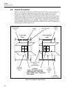
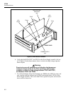
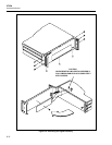
5. Refer to Figure 6-4 for the location of items mentioned in this procedure. Remove
the five retaining screws on the High Voltage Amplifier assembly (A3). (Two screws
secure each side rail, and one seats the board into a mating connector on the
Interconnect assembly.) Lift the High Voltage assembly by pulling on the plastic
wire-tie loops, pivot it, and insert its metal pegs in the two holes on the chassis as
Figure 6-4 shows. This puts the High Voltage Amplifier assembly in the service
position.


