Installation
Selecting Line Voltage
2
2-7
2-7. Selecting Line Voltage
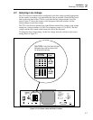
The 5725A arrives from the factory configured for the line voltage normally appropriate
for the country of purchase, or as specified at the time of purchase. Check the line power
label on the rear panel of the 5725A to verify that the line voltage matches local line
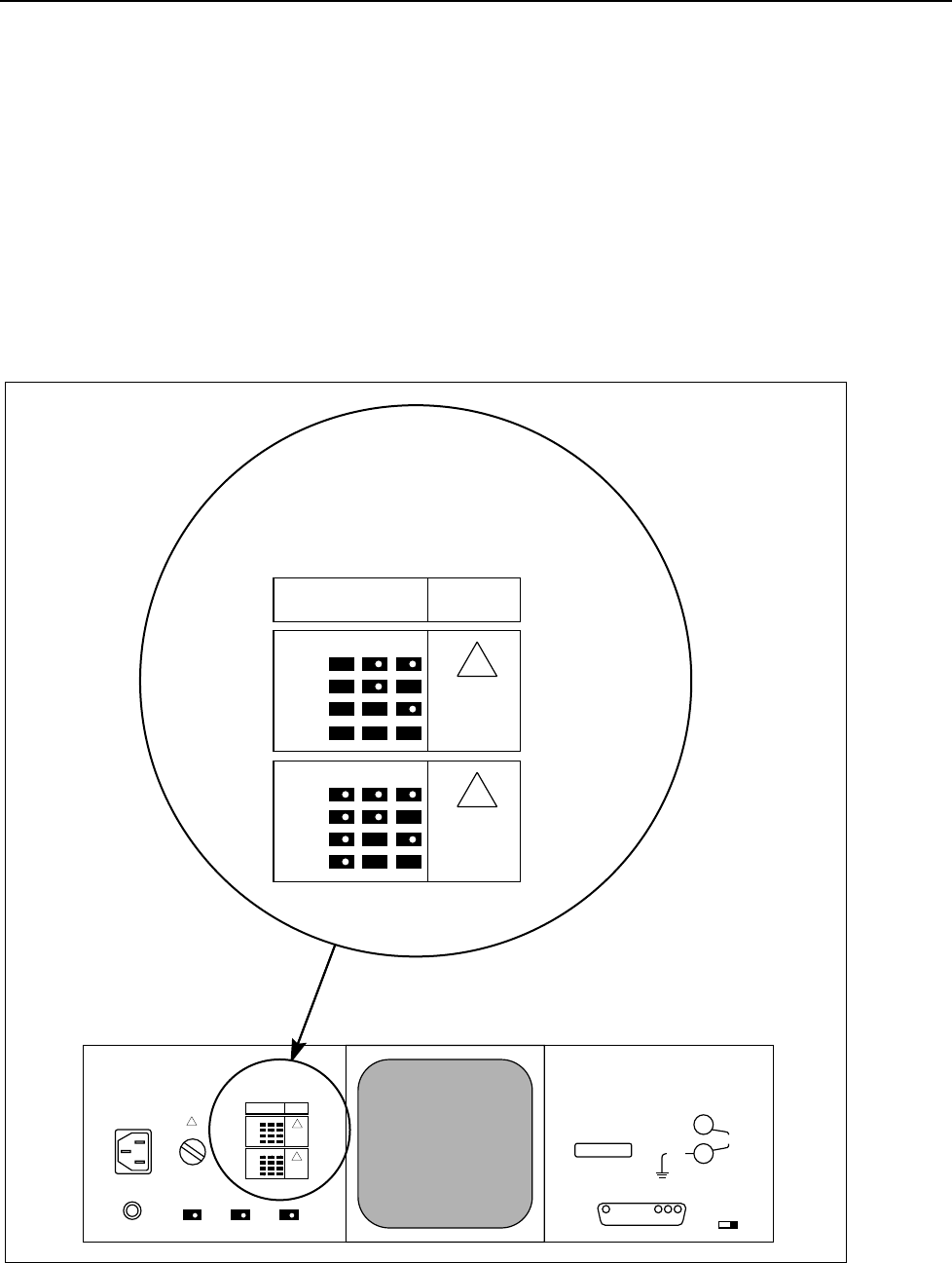
power. Figure 2-3 shows the location of the line power label and switches, and the
switch settings for each line voltage.
The 5725A can be set to operate from eight different nominal line voltages; each voltage
setting has a voltage tolerance of ±10% and a frequency range of 47 to 63 Hz. The line
voltage switches are located on the bottom left side of the rear panel.
To change the line voltage setting, set the line voltage selection switches to the correct
setting shown in Figure 2-3.
100V
110V
115V
120V
S2 S3 S4
VOLTAGE
SELECTION
FUSE
F8A 250V
(FAST)
200V
220V
230V
240V
S2 S3 S4
F4A 250V
(FAST)
JOHN FLUKE MFG. CO., INC.
MADE IN U.S.A.
PATENTS PENDING
NO INTERNAL USER SERVICEABLE
PARTS REFER SERVICE TO
QUALIFIED SERVICE PERSONNEL
TO CLEAN FILTER
REMOVE FROM INSTRUMENT
AND FLUSH WITH WARM
SOAPY WATER
5700A CALIBRATOR
20V PK
MAX
CHASSIS
GROUND
FUSE
WARNING
GROUNDING
CONNECTOR IN POWER CORD
MUST BE CONNECTED TO
ENSURE PROTECTION FROM
ELECTRONIC SHOCK.
47-63 Hz
750VA MAX
CAUTION
FOR FIRE PROTECTION
REPLACE ONLY WITH A 250V FUSE
OF INDICATED RATING.
S4S3S2
100V
110V
115V
120V
S2 S3 S4
VOLTAGE
SELECTION
FUSE
F8A 250V
(FAST)
200V
220V
230V
240V
S2 S3 S4
F4A 250V
(FAST)
CAUTION
FOR FIRE PROTECTION
REPLACE ONLY WITH A 250V FUSE
OF INDICATED RATING.
11A MAX
HI
LO
CALIBRATION
ENABLE NORMAL
CURRENT
OUTPUT
!
!
!
!
!
aq4f.eps
Figure 2-3. Line Power Label and Switch Location


