Maintenance
Enabling Front or Rear Binding Posts
6
6-15
6. Turn over the 5725A so that the top is facing up.
7. Remove the high voltage heat sink assembly as described under “Accessing the High
Voltage Output Transistors", steps 2 through 4.
8. Remove the two screws that secure the Interconnect assembly and pop the assembly
free of the two bosses.
6-15. Enabling Front or Rear Binding Posts
The 5725A comes from the factory configured for front or rear current output as
requested by the purchaser when the system was ordered. Only one output location can
be enabled at a time. You can reconfigure the output location by opening the chassis,
detaching a cable and tying it away, and attaching another cable to a jack on the Current
Amplifier assembly.
Warning
To avoid electrical shock, proceed only after completing the
initial access procedure, which removes line power and checks
for high voltage on the power supply.
Proceed as follows to change the current output location:
1. Perform the Initial Access Procedure.
2. Remove the five retaining screws on the Current Amplifier assembly. Lift the
current amplifier assembly by pulling on the plastic wire-tie loops, and place the
assembly in the service position.
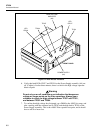
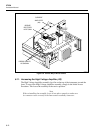
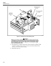
3. Refer to Figure 6-7, and locate J222 on the Current Amplifier assembly.
4. Perform step 5 to change from front to rear, or perform step 6 to change from rear to
front.
5. To enable the rear binding posts and disable the front, remove the cable that goes to
the front binding posts from J222, and plug the cable that goes to the rear binding
posts into J222.
6. To enable the front binding posts and disable the rear, remove the cable that goes to
the rear binding posts from J222, and plug the cable that goes to the front binding
posts into J222.
Use a non-conductive plastic wire tie to secure the unused cable to the right side ventilation slots.


