


FOX 2G Tx/Rx AV • Conguration
Configuration, cont’d
3-4
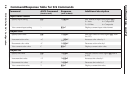
RS-232 Control of Tx and Rx Units
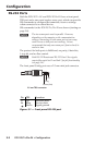
When the FOX 2G Tx/Rx AV is congured by RS-232
commands, some commands are processed by the transmitter
and others are processed by the receiver. The SIS commands do
not distinguish between the two units. The system routes the
commands based on where they are processed.
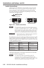
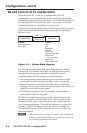
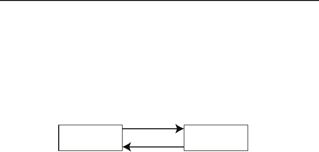
A system block diagram showing which functions are processed
by the transmitter and which are processed by the receiver is
shown below:
Transmitter Receiver
Fiber Link 1
Fiber Link 2
(optional)
Process
Input conguration
Audio gain
Process
Color
Tint
Brightness
Contrast
Video mute
Output conguration
Daisy chain/
loop out mode
Audio mute
Audio output level
Figure 3-4 — System block diagram
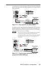
For full functionality, both ber optic links must be enabled.
If only Link 1 is enabled, the ability to congure the system
through SIS commands is limited by the lack of return
communication from the receiver to the transmitter:
All conguration carried out using the transmitter will be •
processed normally because only ber Link 1 is required.
Queries from the transmitter about the status of receiver •
settings will not be processed correctly because ber Link 2 is
required to carry the return signal.
The receiver cannot be used to congure the transmitter •
because ber Link 2 is required.
The lack of communication between the transmitter and the
receiver can result in mismatches in the value settings of the
two units, which may cause confusion with control systems
or software applications. To avoid this confusion, within four
seconds of Link 2 becoming active, the receiver settings are
automatically copied to the transmitter to ensure settings for
both units match.
N
When the receiver settings are copied to the transmitter,
existing transmitter settings are overwritten and it may
be necessary to update those values.