


FOX 2G Tx/Rx AV • Installation and Setup
Installation and Setup, cont’d
2-12
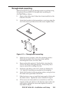
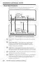
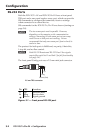
Audio Connections
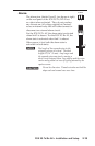
Audio input to the FOX 2G Tx AV and audio output from the
FOX 2G Rx AV are made through the 3.5 mm, 5-pole, captive
screw connectors. Input and output can be mono or stereo
and can be balanced or unbalanced, depending on the wiring
connections (see gure below).
Balanced Audio
Tip
Ring
Tip
Ring
L R
Sleeves
Do not tin the wires!
Unbalanced Audio
Tip
Sleeve
Sleeve
Tip
L R
Figure 2-9 — Audio connections
N
The length of the exposed wires in the stripping process
is critical. The ideal length is 3/16” (5 mm). Any longer
and the exposed wires may touch, causing a short circuit
between them. Any shorter and the wires can be easily
pulled out even if tightly fastened by the captive screws.
C
Do not tin the wires. Tinned wire does not hold its
shape and can become loose over time.
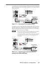
The table below shows the initial gain differences between audio
input/output connectors, using captive screw connectors. The
unbalanced output from the captive screw connector will be half
(-6 dB), regardless of input.
Input Output Gain
Balanced Balanced 0 dB (unity)
Balanced Unbalanced -6 dB (half)
Unbalanced Balanced 0 dB
Unbalanced Unbalanced -6 dB
Additional adjustment of audio gain/attenuation can be made
using SIS commands (see page 3-8).
N
The Audio LED lights up immediately when the
transmitter detects an audio signal 35 dB below the
nominal level. It remains lit until the audio signal drops
below that threshold continuously for 10 seconds.