


FOX 2G Tx/Rx AV • Installation and Setup
2-9
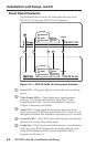
Rear Panel Features
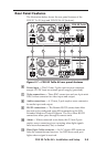
The illustration below shows the rear panel features of the
FOX 2G Tx AV (top) and FOX 2G Rx AV (bottom):
FOX 2G Tx AV
Y/VID
I
N
P
U
T
S
OVER FIBER REMOTE
RS-232
Tx Rx Tx Rx
AUDIO
LR
ALARM
12
R-Y
B-Y/C
S-VID
OPTICAL
POWER
12V
0.6A MAX
RxTx
FOX 2G Rx AV
Y/VID
O
U
T
P
U
T
S
Tx Rx Tx Rx
AUDIO
LR
RxTx
ALARM
12
R-Y
B-Y/C
S-VID
OPTICAL
POWER
12V
0.6A MAX
OVER FIBERREMOTE
RS-232
6 7
8 9 10 11
Figure 2-7 — FOX 2G Tx/Rx AV rear panel features
f
Power input — This 3.5 mm, 2-pole captive screw connector
accepts 12 VDC from an external power supply (provided).
g
Video connections — Three BNC connectors and one 4-pin mini
DIN S-video connector for video input and output.
h
Audio connections — A 3.5 mm, 5-pole captive screw connector
for audio input and output.
i
RS-232 connections — The Remote RS-232 connections allow
the units to be congured using SIS commands or the FOX
Extender Windows Control Program. The Over Fiber RS-232
connections allow pass-through to remote units.
j
Alarm — When connected to an alarm, this 3.5 mm 2-pole
captive screw connector gives a warning when light signals
have been disconnected, lost, or broken.
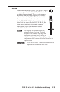
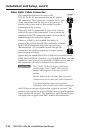
k
Fiber Optic Cable connector — An LC duplex SFP connector
links the transmitter and receiver. An LED above each port
lights when a signal is received.