


DVC 501 SD • Installation 5
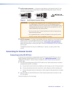
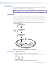
f Audio output connector — Connect an audio device to this female 5-pole 3.5 mm
captive screw connector for balanced or unbalanced analog audio output. Wire the
connector as shown below.
Do not tin the wires!
Balanced Audio Output
Tip
Ring
Tip
Ring
LR
Sleeves
Unbalanced Audio Output
Tip
Tip
LR
Sleeves
Figure 4. Audio Output Connector Wiring
CAUTIONS: • The length of the exposed wires in the stripping process is critical.
The ideal length is 3/16 inches (5 mm). If the exposed portion is
longer, the wires may touch, causing a short circuit between them. If
the exposed wires are shorter, they can be easily pulled out, even if
tightly fastened by the captive screws.
• Do not tin the wires. Tinned wire does not hold its shape and can
become loose over time.
• For unbalanced audio, connect the sleeves to the ground contact.
DO NOT connect them to negative (–) contacts.
g RS-232 connector — Connect a host device such as a computer or touch panel control
system to the Tx, Rx, and _ (ground) pins of this 5-pole captive screw connector for
serial control of the DVC by SIS commands (see “Connecting to the RS-232 Port,”
below, for information on wiring this port). The first and second pins of this connector
are not used.
The default protocol for this port is 9600 baud, 1 stop bit, no parity, and no flow
control.
Connecting for Remote Control
Connecting to the RS-232 Port
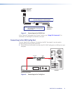
To connect your computer or control system to the DVC rear panel RS-232 port, use an
Extron Universal Control cable (UC50' or UC100'; see “Optional Accessories” in the
“Reference Information” section for part numbers) or other female 9-pin-to-bare-wire
RS-232 cable.
1. Wire the unterminated end of the RS-232 cable to the 3-pole captive screw connector,
provided with the DVC, as follows:
a. Connect the transmit wire to the middle pin, which plugs into the Tx (transmit) port.
b. Connect the receive wire to the fourth pin, which plugs into the Rx (receive) port.
c. Connect the ground wire to the last pin, which plugs into the ground port, marked
with _.
2. Plug the cable into the RS-232 portion of the 5-pole captive screw connector on the
DVC rear panel.
See the illustration on the next page.