


DVC 501 SD • Installation 4
Rear Panel
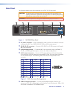
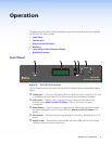
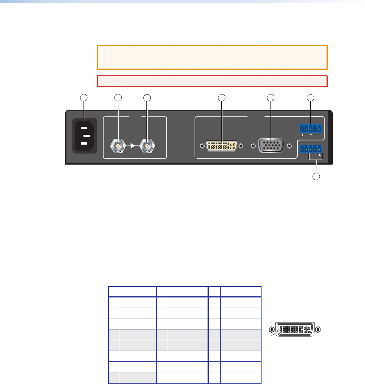
The illustration below shows the connectors on the DVC 501 SD rear panel.
CAUTION: Use electrostatic discharge precautions (be electrically grounded) when
making connections. Electrostatic discharge (ESD) can damage equipment,
although you may not feel, see, or hear it.
WARNING: Remove power from the system before making any connections.
100-240V ~ 0.3A MAX
50/60 Hz
3G/HD/SD-SDI
BUFFERED
INPUT
LOOP-THROUGH
RGB/R-Y,Y,B-Y
OUTPUT
DVI-D
LR
RS-232
N/A Tx
Rx
AUDIO
1
2
4
5
6
3
7
Figure 2. DVC 501 SD Rear Panel
a AC power connector — Plug a standard IEC power cord into this male IEC connector
to connect the DVC to a 100 to 240 VAC, 50 Hz or 60 Hz power source.
b 3G/HD/SD-SDI connector — Connect a 3G, HD-SDI, or SD-SDI source to this female
BNC input connector.
c Buffered loop-through — This female BNC input connector passes a buffered 3G,
HD-SDI, or SD-SDI signal through to a monitor or a video storage device.
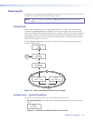
d DVI-D output connector — Connect a DVI output device to this female single-link
DVI-I connector (only the digital pins are enabled). RGB or YUV color space is available
on this buffered output. The following table shows the pin assignments for this
connector.
8 Not used 16 Hot plug detect 24 TMDS clock–
Pin
Signal
Pin Signal
Pin
Signal
1 TMDS data 2– 9 TMDS data 1– 17 TMDS data 0–
2 TMDS data 2+ 10 TMDS data 1+ 18 TMDS data 0+
3 Ground (2/4 ) 11 Ground (1/3) 19 Ground (0/5)
4 Not used 12 Not used 20 Not used
5 Not used 13 Not used 21 Not used
6 DDC clock 14 +5 V power 22 Ground (clock)
7 DDC data 15 Ground (for 5 V) 23 TMDS clock+
1
8
17
24
9
Figure 3. DVI-D Connector Pin Assignments
e RGB/YUV output connector — Connect an RGB (RGBHV, RGBS, RGsB) or YUV
component (R-Y, Y, B-Y) display device to this female 15-pin HD connector. RGB or YUV
color space is available on this buffered output.