


Reference Manual
00809-0100-4697, Rev EA
October 2011
Rosemount 848T
D-2
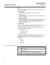
10 XD_SCALE None The high and low scale values, engineering units code, and number of digits to
the right of the decimal point associated with the channel input value. The
XD_SCALE units code must match the units code of the measurement channel in
the transducer block. If the units do not match, the block will not transition to MAN
or AUTO.
11 OUT_SCALE None The high and low scale values, engineering units code, and number of digits to the
right of the decimal point associated with OUT when L_TYPE is not direct.
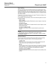
12 GRANT_DENY None Options for controlling access of host computers and local control panels to
operating, tuning, and alarm parameters of the block. Not used by device.
13 IO_OPTS None Allows the selection of input/output options used to alter the PV. Low cutoff enabled
is the only selectable option.
14 STATUS_OPTS None Allows the user to select options for status handling and processing. The options
supported in the AI block are the following:
Propagate fault forward
Uncertain if limited
Bad if limited
Uncertain if Manual mode.
15 CHANNEL None The CHANNEL value is used to select the measurement value. Configure the
CHANNEL parameter before configuring the XD_SCALE parameter. Refer to Table
3-5 on page 3-11.
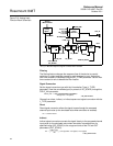
16 L_TYPE None Linearization type. Determines whether the field value is used directly (Direct), is
converted linearly (Indirect), or is converted with the square root (Indirect Square
Root).
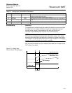
17 LOW_CUT % If percentage value of transducer input fails below this, PV = 0.
18 PV_FTIME Seconds The time constant of the first-order PV filter. It is the time required for a 63% change
in the PV or OUT value.
19 FIELD_VAL Percent The value and status from the transducer block or from the simulated input when
simulation is enabled.
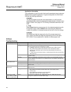
20 UPDATE_EVT None This alert is generated by any change to the static data.
21 BLOCK_ALM None The block alarm is used for all configuration, hardware, connection failure or system
problems in the block. The cause of the alert is entered in the subcode field. The first
alert to become active will set the Active status in the Status parameter. As soon as
the Unreported status is cleared by the alert reporting task, another block alert may
be reported without clearing the Active status, if the subcode has changed.
22 ALARM_SUM None The summary alarm is used for all process alarms in the block. The cause of the
alert is entered in the subcode field. The first alert to become active will set the
Active status in the Status parameter. As soon as the Unreported status is cleared
by the alert reporting task, another block alert may be reported without clearing the
Active status, if the subcode has changed.
23 ACK_OPTION None Used to set auto acknowledgment of alarms.
24 ALARM_HYS Percent The amount the alarm value must return within the alarm limit before the associated
active alarm condition clears.
25 HI_HI_PRI None The priority of the HI HI alarm.
26 HI_HI_LIM EU of PV_SCALE The setting for the alarm limit used to detect the HI HI alarm condition.
27 HI_PRI None The priority of the HI alarm.
28 HI_LIM EU of PV_SCALE The setting for the alarm limit used to detect the HI alarm condition.
29 LO_PRI None The priority of the LO alarm.
30 LO_LIM EU of PV_SCALE The setting for the alarm limit used to detect the LO alarm condition.
31 LO_LO_PRI None The priority of the LO LO alarm.
32 LO_LO_LIM EU of PV_SCALE The setting for the alarm limit used to detect the LO LO alarm condition.
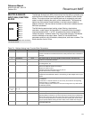
33 HI_HI_ALM None The HI HI alarm data, which includes a value of the alarm, a timestamp of
occurrence and the state of the alarm.
34 HI_ALM None The HI alarm data, which includes a value of the alarm, a timestamp of occurrence
and the state of the alarm.
35 LO_ALM None The LO alarm data, which includes a value of the alarm, a timestamp of occurrence
and the state of the alarm.
Table D-1. Analog Input Function Block Parameters
Number Parameter Units Description