


Reference Manual
00809-0100-4697, Rev EA
October 2011
Rosemount 848T
2-8
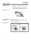
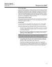
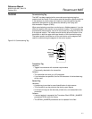
GROUNDING The 848T transmitter provides input/output isolation up to 620 V rms.
NOTE
Neither conductor of the fieldbus segment can be grounded. Grounding out
one of the signal wires will shut down the entire fieldbus segment.
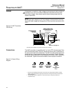
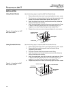
Shielded Wire
Each process installation has different requirements for grounding. Use the
grounding options recommended by the facility for the specific sensor type or
begin with grounding option 1 (most common).
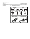
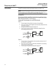
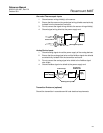
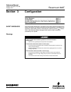
Ungrounded Thermocouple, mV, and RTD/Ohm Inputs
Option 1:
1. Connect signal wiring shield to the sensor wiring shield(s).
2. Ensure the shields are tied together and electrically isolated from the
transmitter enclosure.
3. Only ground shield at the power supply end.
4. Ensure that the sensor shield(s) is electrically isolated from the
surrounding grounded fixtures.
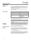
Option 2:
1. Connect sensor wiring shield(s) to the transmitter enclosure (only if
the enclosure is grounded).
2. Ensure the sensor shield(s) is electrically isolated from surrounding
fixtures that may be grounded.
3. Ground signal wiring shield at the power supply end.
Sensor Wires
Power
Supply
Shield ground point
848T
Sensor Wires
Power
Supply
Shield ground points
848T