


Reference Manual
00809-0100-4697, Rev EA
October 2011
C-5
Rosemount 848T
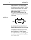
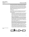
There may be many LM devices on a segment but only the LAS is actively
controlling communication traffic. The remaining LM devices on the segment
are in a stand-by state, ready to take over if the primary LAS fails. This is
achieved by constantly monitoring the communication traffic on the bus and
determining if activity is not present. Since there can be multiple LM devices
on the segment when the primary LAS fails, the device with the lowest node
address will become the primary LAS and take control of the bus. Using this
strategy, multiple LAS failures can be handled with no loss of the LAS
capability of the communications bus.
LAS Parameters
There are many bus communication parameters but only a few are used. For
standard RS-232 communications, the configuration parameters are baud
rate, start / stop bits, and parity. The key parameters for H1 F
OUNDATION
fieldbus are as follows.
• Slot Time (ST) – Used during the bus master election process. It is the
maximum amount of time permitted for device A to send a message to
device B. Slot time is a parameter which defines a worst case delay
which includes internal delay in the sending device and the receiving
device. Increasing the value of ST slows down bus traffic because a
LAS device must wait longer prior to determining that the LM is down.
• Minimum Inter-PDU Delay (MID) – The minimum gap between two
messages on the fieldbus segment or it is the amount of time between
the last byte of one message and the first byte of the next message.
The units of the MID are octets. An octet is 256 s, hence the units for
MID are approximately
1
/4 ms. This would mean an MID of 16 would
specify approximately a minimum of 4 ms between messages on the
Fieldbus. Increasing the value of MID slows down bus traffic because a
larger “gap” between messages occurs.
• Maximum Response (MRD) – Defines the maximum amount of time
permitted to respond to an immediate response request, e.g. CD, PT.
When a published value is requested using the CD command, the MRD
defines how long before the device publishes the data. Increasing this
parameter will slow down the bus traffic by decreasing how fast CDs
can be put onto the network. The MRD is measured in units of ST.
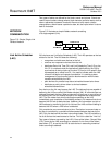
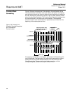
• Time Synchronization Class (TSC) – A variable that defines how long
the device can estimate its time before drifting out of specific limits. The
LM will periodically send out time update messages to synchronize
devices on the segment. Decreasing the parameter number increases
the number of times that time distribution messages must be published,
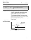
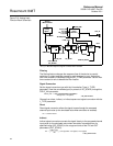
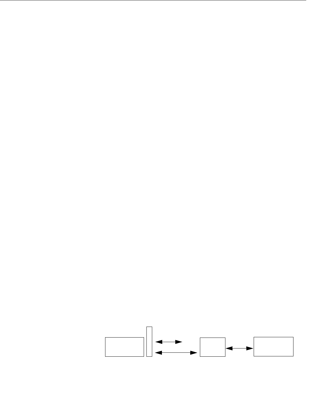
increasing bus traffic and overhead for the LM device. See Figure C-3.
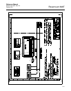
Figure C-3. LAS Parameter
diagram
FB 1
C
D
Data
FB 2
MID
MID x ST
MID