Reference Manual
00809-0100-4697, Rev EA
October 2011
D-11
Rosemount 848T
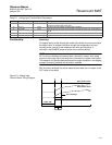
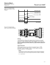
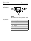
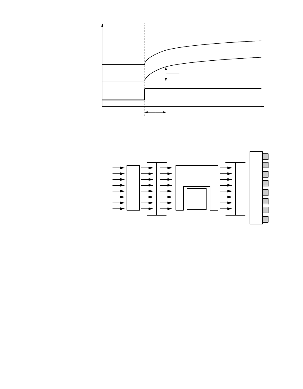
Figure D-3. Multiple Analog
Input Function Block Timing
Diagram
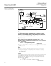
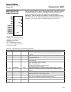
Figure D-4. Multiple Analog
Input Function Block Schematic
Filtering
The filtering feature changes the response time of the device to smooth
variations in output readings caused by rapid changes in input. Adjust the
filter time constant (in seconds) using the PV_FTIME parameter (same value
applied to eight channels). Set the filter time constant to zero to disable the
filter feature.
Signal Conversion
Set the signal conversion type with the Linearization Type (L_TYPE)
parameter. Choose from direct, indirect, or indirect square root signal
conversion with the L_TYPE parameter.
Direct
Direct signal conversion allows the signal to pass through the accessed
channel input value (or the simulated value when simulation is enabled).
PV_FTIME
63% of Change
OUT (mode in man)
OUT (mode in auto)
PV
Time (seconds)
FIELD_VAL
OUT_1
OUT_2
OUT_3
OUT_4
OUT_5
OUT_6
OUT_7
OUT_8
OUT_SCALEXD_SCALE
Mode Logic
L_TYPE
& Filter
Ch 1
Ch 2
Ch 3
Ch 4
Ch 5
Ch 6
Ch 7
Ch 8
Simulate
PV Channel Value=


