


Reference Manual
00809-0100-4697, Rev EA
October 2011
2-5
Rosemount 848T
RTD or Ohm Inputs
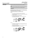
Various RTD configurations, including 2-wire and 3-wire are used in industrial
applications. If the transmitter is mounted remotely from a 3-wire RTD, it will
operate within specifications, without recalibration, for lead wire resistances of
up to 60 ohms per lead (equivalent to 6,000 feet of 20 AWG wire). If using a
2-wire RTD, both RTD leads are in series with the sensor element, so errors
can occur if the lead lengths exceed one foot of 20 AWG wire. Compensation
for this error is provided when using 3-wire RTDs.
Thermocouple or Millivolt Inputs
Use appropriate thermocouple extension wire to connect the thermocouple to
the transmitter. Make connections for millivolt inputs using copper wire. Use
shielding for long runs of wire.
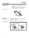
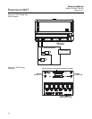
Analog Inputs
The analog connector converts the 4–20 mA signal to a 20–100 mV signal
that can be read by the 848T and transmitted using F
OUNDATION fieldbus.
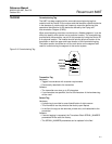
Use the following steps when installing the 848T with the analog connector:
1. The 848T, when ordered with option code S002, comes with four analog
connectors. Replace the standard connector with the analog connector
on the desired channels.
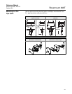
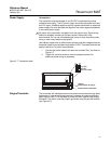
2. Wire one or two analog transmitters to the analog connector according to
Figure 2-5. There is space available on the analog connector label for
identification of the analog inputs.
NOTE
Power supply should be rated to support the connected transmitter(s).
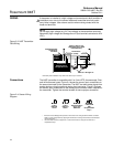
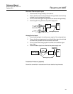
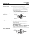
3. If the analog transmitters can communicate using HART protocol, the
analog connectors are supplied with the ability to switch in a 250 ohm
resistor for HART communication (see Figure 2-6).
One switch is supplied for each input (top switch for “A” inputs and
bottom switch for “B” inputs). Setting the switch in the “ON” position (to
the right) bypasses the 250 ohm resistor. Terminals are provided for each
analog input to connect a Field Communicator for local configuration.