Reference Manual
00809-0100-4697, Rev EA
October 2011
2-7
Rosemount 848T
Power Supply Connections
The transmitter requires between 9 and 32 VDC to operate and provide
complete functionality. The DC power supply should provide power with less
than 2% ripple. A fieldbus segment requires a power conditioner to isolate the
power supply filter and decouple the segment from other segments attached
to the same power supply.
All power to the transmitter is supplied over the signal wiring. Signal wiring
should be shielded, twisted pair for best results in electrically noisy
environments. Do not use unshielded signal wiring in open trays with power
wiring or near heavy electrical equipment.
Use ordinary copper wire of sufficient size to ensure that the voltage across the
transmitter power terminals does not go below 9 VDC. The power terminals are
polarity insensitive. To power the transmitter:
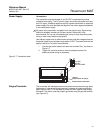
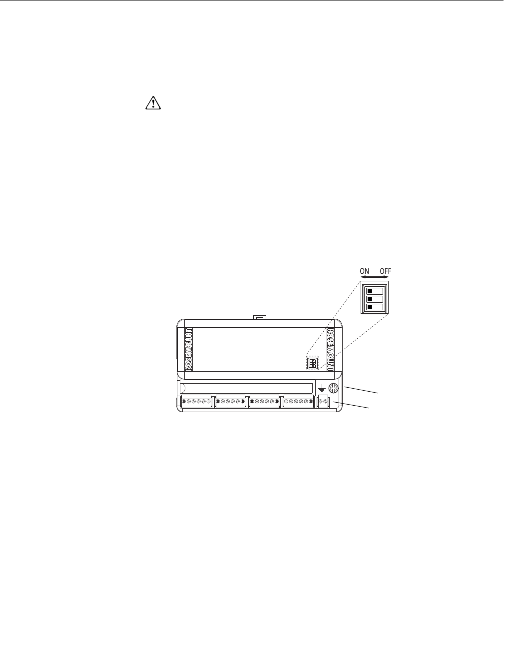
1. Connect the power leads to the terminals marked “Bus,” as shown in
Figure 2-7.
2. Tighten the terminal screws to ensure adequate contact. No
additional power wiring is necessary.
Figure 2-7. Transmitter Label
Surges/Transients The transmitter will withstand electrical transients encountered through static
discharges or induced switching transients. However, a transient protection
option (option code T1) is available to protect the 848T against high-energy
transients. The device must be properly grounded using the ground terminal
(see Figure 2-7).
NOT USED
SECURITY
SIMULATE ENABLE
Connect Power Leads Here
Ground
(required with T1 option)


