ENGLISH
23
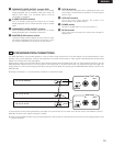
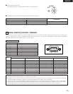
2 Hard disk drive access lamp
The access lamp when a hard disk drive is added is “ACCESS HDD”.
PCC
ACCESS
HDD
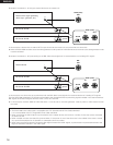
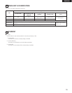
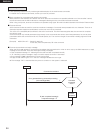
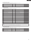
2 The following shows the order of priority when the power is turned on.
When power turned on
PCC (PC card slot (drive))
Hard disk driveNone
PC card slot (drive) *1Loaded
Current drive
HDD (hard disk drive)
Installed
Installed
*1) The current drive does not switch automatically to the HDD when the PC card is ejected.
14
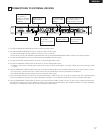
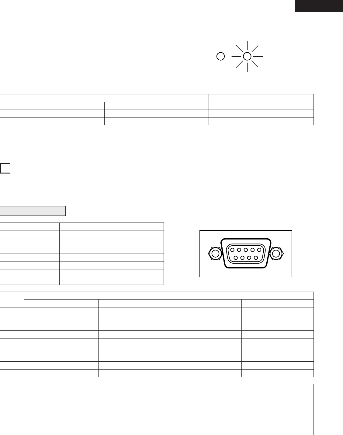
SERIAL REMOTE CONTROL TERMINAL
The serial remote control terminal on the DN-V1700’s rear panel can be used to connect the terminal software of a computer, etc.,
allowing a wide variety of control possibilities through serial remote control. The terminal is compatible with both RS232C and RS422A
standards, selected with the selector switch on the rear panel.
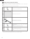
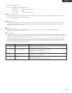
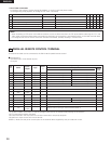
Hardware specifications
D-sub female 9 pins
Standards
Connector type
8 bitsData length
9,600 bpsBaud rate
None
Flow control
Asynchronous synchronizationSynchronization
None
Parity
Conforming to RS232C and RS422A
1 bitStop bit
15
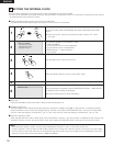
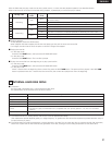
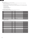
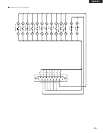
69
1
2
3
4
5
6
7
8
Pin no.
_
Output
Input
_
_
_
Output
Input
_
TXD (RETURN)
RXD
_
_
GND
TXD
RXD (RETURN)
RS422A (selector switch pressed in)
_
Output
Input
_
_
_
_
_
_
TXD
RXD
_
GND
_
_
_
RS232C (selector switch popped out)
Signal name Input/output Signal name Input/output
9
____
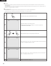
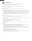
NOTES:
• Use a serial straight through cable for connection to a computer.
• Be sure to turn the power of both the DN-V1700 and the control device off when connecting the serial cable and switching
between RS232C and RS422A. Failure to do so could damage the DN-V1700 or the control device.
Be sure to switch to the proper RS232C or RS422A setting for the communications hardware specifications of the control device.
• Signals other than TXD and RXD (DTR signals, for example) cannot be used on the DN-V1700. If reception control of such signals
is being performed on the control device, take the necessary software or hardware measures on the control device.


