ENGLISH
14
6
NAME AND FUNCTIONS OF PARTS
(See page 3.)
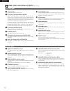
(1) Front panel
q
Internal HDD
This is the internal hard disk drive.
w
IC memory card eject button (EJECT)
Press this to eject the IC memory card. Be sure the stop
mode is set or the power is turned off when ejecting the IC
memory card. In particular, never eject the card when the IC
memory card access lamp is flashing or lit (except when the
access lamp is flashing to indicate an error).
If the eject operation is performed when the card is being
accessed, the data may be lost and the set may be
damaged. Should this happen, “reboot!!!” may output from
the set’s video output and the set may be reset forcibly.
e
IC memory card slot (drive)
This is where the IC memory card is inserted. Be sure to
load the IC memory card securely.
r
POWER indicator
This lights when the set’s power is on.
t
IC memory card access lamp (ACCESS PCC)
This lights or flashes when the IC memory card is being
accessed.
y
Hard disk access lamp (ACCESS HDD)
This lights or flashes when the hard disk drive is being
accessed.
u
PLAY/PAUSE button
In the normal play mode with a file selected, press this in the
stop or pause mode to start playback. When pressed during
playback, the pause mode is set.
i
STOP button
Press this to stop playback. During script playback, press the
button for 2 seconds or more to stop script playback.
o
SKIP 8 button
Press this to search for the previous file in the currently set
sorting order.
!0
SKIP 9 button
Press this to search for the next file in the currently set
sorting order.
!1
OSD/TIME SET button
Press this to turn the OSD (on-screen display) on and off.
Use this button together with the STOP button to set the
time.
!2
SELECT button
Use this to change the current directory.
Use this button together with the STOP button to change
the current drive.
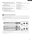
(2) Rear panel
q
PARALLEL REMOTE terminal
This is the terminal for parallel control from an external
device.
w
SERIAL REMOTE terminal
This is the terminal for serial control from an external device.
Use a serial straight through cable for connection to a
computer.
e
RS232C/RS422A selector switch
Use this switch to select the SERIAL REMOTE terminal’s
interface.
Set to the back for RS422A, to the front for RS232C.
r
ETHERNET terminal
This is a 10 Base-T/100 Base-TX LAN connector.
t
DIGITAL AUDIO OUTPUT terminal
This is an SPDIF digital audio output. Connect an amplifier,
etc., allowing digital input.
y
ANALOG AUDIO OUTPUT terminal (XLR)
This is a balanced type analog audio output using an XLR
type connector.
[Pin layout] 1: Ground (G)
2: Hot (H)
3: Cold (C)
u
ANALOG AUDIO OUTPUT terminal (RCA)
This is an analog audio output. Connect it to an amplifier or
monitor speaker with an analog audio input using an RCA
pin-plug cable.
i
COMPOSITE VIDEO OUTPUT terminal (BNC)
This is a composite video output. Connect it to a monitor
display equipped with a composite video input using a 75
Ω/ohms BNC cable. The connected device must be
terminated at 75 Ω/ohms.


