8
ENGLISH
VIDEO
MON.OUT
S VIDEO
IN IN ININ OUT
TV/DBS
V.AUX
VCR
R
L
AUDIO
IN OUT IN IN ININ OUT
V.AUXTV/DBS VCR
CDR/
TAPE
PRE OUT
SUB WOOFER
IN IN OUT
V.AUXTV/DBS
(OPTICAL)
DIGITAL
SPEAKER SYSTEMS
6 16
R
L
R
L
IMPEDANCE
CENTER SURROUNDFRONT
MON.OUT
Y CB CR
AM
FM COAX. 75
LOOP
ANT.
COMPONENT VIDEO OUT
OPTICAL
IN
OUTPUT
L
R
INPUT
LR
L
R
R
L
L
R
L
R
B
7
CONNECTIONS
• Do not plug in the AC cord until all connections have been
completed.
• Be sure to connect the left and right channels properly (left with
left, right with right).
• Insert the plugs securely. Incomplete connections will result in the
generation of noise.
• Note that binding pin plug cords together with AC cords or placing
them near a power transformer will result in generating hum or
other noise.
• Noise or humming may be generated if a connected audio
equipment is used independently without turning the power of this
unit on. If this happens, turn on the power of the this unit.
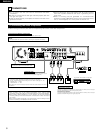
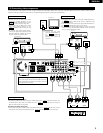
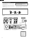
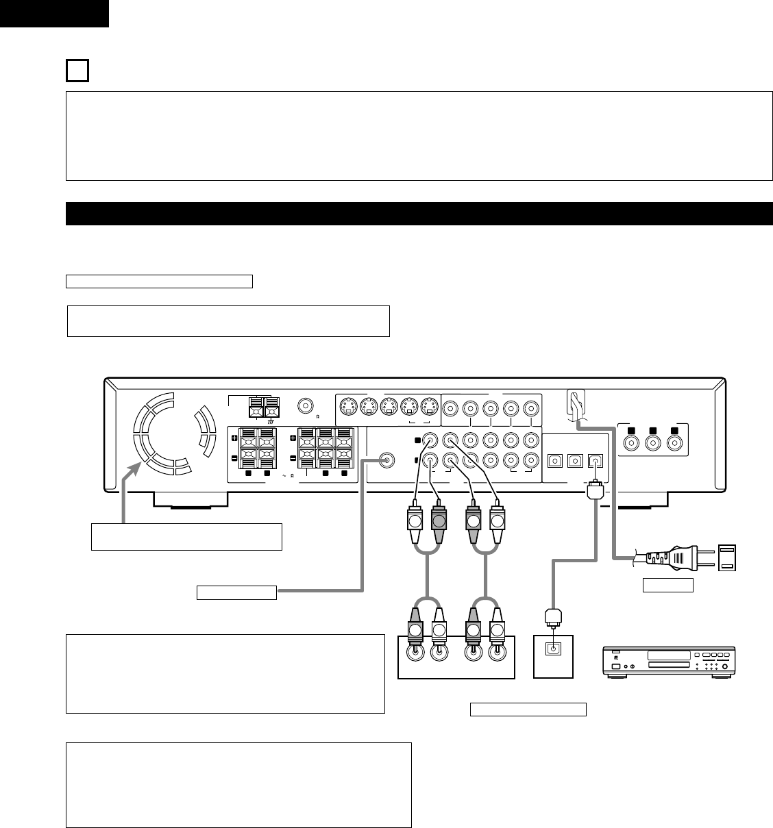
(1) Connecting the audio components
• When making connections, also refer to the operating instructions of the other components.
Subwoofer jack
Connect the internal amplifier’s subwoofer to the
subwoofer terminal. (Refer to page 14.)
•
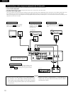
To conduct digital recording onto a digital recorder (CD recorder, MD recorder, etc.)
while playing Dolby Digital, 96 kHz PCM sources on this DVD player.
•
Set the “AUDIO SETUP” default setting as shown below. (See page 77, 78.)
• “DIGITAL OUT”
→ “PCM”
“LPCM SELECT” → “ON”
Playing DVDs with incorrect settings may result noise that could damage your ears or
the speakers.
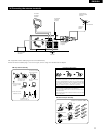
AC CORD
AC 120 V, 60 Hz
Connecting a recorder
Connections for recording:
Connect the tape deck’s recording input jacks (LINE IN or REC) to this unit’s tape
recording (CDR/TAPE OUT) jacks using pin plug cords.
Connections for playback:
Connect the tape deck’s playback output jacks (LINE OUT or PB) to this unit’s tape
playback (CDR/TAPE IN) jacks using pin plug cords.
CD recorder, MD recorder or Tape deck
Route the connection cords, etc., in such a way
that they do not obstruct the ventilation holes.
Connecting the DIGITAL (optical) jacks
Use these for connections to audio equipment with digital (optical) output.
NOTES:
• Use optical cables for optical connections, removing the cap before connecting.
NOTE:
•
Track numbers may not be added automatically when making digital
recordings of CDs being played on the ADV-700 onto a connected recorder.
•
When making digital recordings on a CD recorder, set the CD recorder’s
recording setting to manual and add track numbers (track marks) manually as
you record.
•
When making digital recordings on an MD recorder, use the editing function
after the recording is completed to divide the tracks.


