


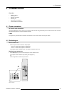

4. Connections
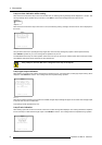
5. Press ENTER.
The internal system will scan the inputs and displays the result in the Input Slots menu.
6. Push the cursor key ↑ or ↓ to select the first or second slot. (menu 4-6)
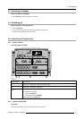
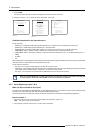
ADJUSTMENT MODE
Select a path from below :
RANDOM ACCESS
INSTALLATION
SERVICE
Select with ↑ or ↓
then <ENTER>
<EXIT> to return
Menu 4-4
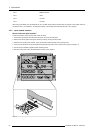
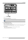
INSTALLATION
INPUT SLOTS
800 PERIPHERAL
SOURCE SWITCHING
NO SIGNAL
CONTRAST ENHANCEMENT
CONVERGENCE
CONFIGURATION
LENS
QUICK ACCESS KEYS
OSD
INTERNAL PATTERNS
Select with ↑ or ↓
then <ENTER>
<EXIT> to return
Menu 4-5
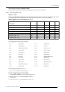
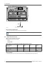
INPUT SLOTS
Slot Module type [config]
1. RGB-SS [CV]
2. RGB-SOG
3. SDI
4. SDI
______________
1. DVI OUTPUT [DVI input]
Select with ↑ or ↓
then <ENTER>
<EXIT> to return
Menu 4-6
Possible indications on the input slot menu.
For the input side:
• RGS-SS [CV or HS&VS] = RGB analog signals, separate sync is composite sync or horizontal and vertical sync.
• RGB-SS [CV] = RGB analog signals, separate sync is composite video.
• RGB-SOG [SOG or 3LSOG] = RGB analog signals, sync on green is composite sync or composite tri-level sync.
• COMPONENT VIDEO - SS [SS or 3LSS] = separate sync is composite sync or composite tri-level sync.
• COMPONENT VIDEO - SOY [SOY or 3LSOY] = component video with composite sync on Y or composite tri-level s
ync on Y.
•VIDEO
•S-VIDEO
•DVI
When changing from an analog signal on the 5 cable module to the PanelLink input the indication led on the front panel of the module
will switch from the 5 cable input to the DVI (PanelLink) input also.
For the output on fixed slot 1:
• DVI input : DVI in signal is looped through to the DVI out connector as it is.
• Active image : active image signal, what ever the input is, is available in DVI on theDVI output signal (processing is incorporated
in the signal). Set the minimum delay in Installation > Advanced processing to OFF.
• DVI resync : DVI in signal is resyncronized with a stable clock and put on the DVI out connector
When using an RCVDS 05 with a 5 cable output module, connect these 5 cables to this fixed 5
-input slot (slot
1) of the projector. All sources of the RCVDS can now be accepted by the projector.
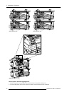
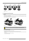
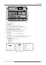
4.5.5 Serial Digital Input (slot 3 & 4)
What can be connected to this input?
This input is full compatibility with digital Betacam, or other digital video sources. This avoids the need for analog video processing
anywhere in the video production chain and guarantees the ultimate image quality.
An active loop-through of the SDI input signal is provided for monitoring or for double and or triple stacking applications.
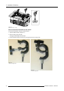
How to connect ?
1. Connect the output of your SDI source to the input BNC of the SDI input. (image 4-5)
Note: The input is always 75 Ω terminated.
2. If loop through is needed, use the OUT to connect to the next device.
28
R5976654 SLM R12+ 09022004