


Introduction
22
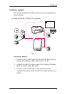
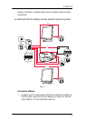
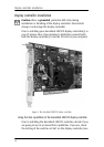
2. Connect the other video output of the first display controller
to the BNC input of the projector by means of the DVI-to-5
BNC cable (15 m / 50 ft) (Video 2 in the illustration above).
3. Connect one PC video output of the second display controller
to the DVI video input of the second display by means of the
DVI cable (Video 3 in the illustration above).
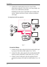
4. Connect the other video output of the second display
controller to the Sub-D15 (VGA) input of the projector by
means of the DVI-to-VGA cable (15 m / 50 ft) (Video 4 in the
illustration above).
5. Connect a free PC COM port to the RS-232 connector of the
projector by means of the D-Sub9-to-D-Sub9 cable (15 m /
50 ft).
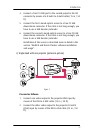
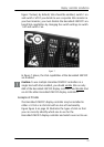
6. Connect the I-Guard optical sensor to a free PC USB
downstream connector. If the cable is not long enough, you
have to use a USB booster/extender.
Installation of the sensor is described more in detail in the
section “MediCal and Dicom Theater software installation
and usage”.
Important:
Do not connect the two display inputs nor the two projector
inputs to the same display controller. In other words, to each
display controller, a display input and a projector input must be
connected.