


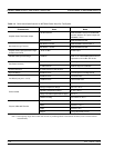
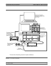

Step 3. Install the four RF cables between the rear of the MS462XC
and the Test Set. Torque the cables to 8 inch-pounds (SMA
Connectors) or 12 inch-pounds (Type N connectors). Table 2-1
lists the applicable connectors by designation or function.
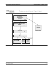
Step 4. Install the control cable between the External I/O connector
on the rear panel of the MS462XC and the Control In connec
-
tor on the rear panel of the Test Set.
Step 5. Connect the GPIB cable from IEEE-488.2 connector on the
rear panel of the MS462XC to the PC/System Controller.
(Note: This cable is not supplied with the ME7840A PATS.)
Step 6. Connect an AC power cord to each of the three-prong connec
-
tors on the rear panel of the Test Set and the MS462XC.
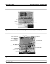
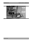
Step 7. (Optional, for drain current PAE measurements) Connect the
current probe cable BNC connector to the Ext. Analog In con
-
nector on the rear of the MS462XC as shown in Figure 2-4
(page 2-5).
INSTALLATION - HARDWARE INSTALLATION
2-4 ME 7840A OMM
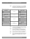
VNMS - FRONT
Connects To:
TEST SET - FRONT
PORT 1 “TO PORT 1”
PORT 2 “TO PORT 2”
PORT 3 “TO PORT 3”
TEST SET - FRONT
Connects To:
DEVICE UNDER TEST
TEST PORT 1 DUT INPUT
TEST PORT 2 DUT OUTPUT
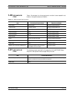
VNMS - REAR
Connects To:
MS4782X -REAR
PORT a1 PORT a1
PORT a2 PORT a2
PORT b1 PORT b1
PORT b2 PORT b2
MS4782D TEST SET - REAR
Connects To
(See Figure 1-2 for a block diagram)
CIRCULATOR
C1 Circulator 1 or C2
C2 Circulator 2 or C1
C3 Circulator 3 or Open
Table 2-1. RF Cable Connection