


11-APR-06 Rev E OMACS3000
8 of 51
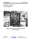
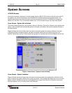
System Description
DS-5 STOP Illuminates steady YELLOW when the Emergency Stop Switch is depressed.
DS-6 MICRO RESET Illuminates steady RED when MPU-17 microprocessor is in a reset condition. Blinks
RED in a continuous reset condition or buss failure.
DS-7 POWER Illuminates steady GREEN when MC-2 is receiving +/-12 VDC
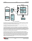
Dual VFD Motor Drive Card (MD-3)
The Dual VFD Motor Drive Card (center card) handles control, status and fault reporting of the azimuth and
elevation Variable Frequency Drive Units (VFD's). The Dual VFD Motor Drive Card has two fault indicators.
The MD-3 provides the following fault indicators that are viewable from the face of the card:
DS-1 OVERLOAD Illuminates Steady RED when AZ, EL, or both AZ and EL axis motors are drawing
excessive current. A slow RED blink (500ms) indicates loss of communication with
the MPU-17.
DS-2 FAULT Illuminates RED when either VFD is in a fault condition. A slow RED blink (500 ms)
indicates loss of communication with the MPU-17. A fast RED blink (250 ms)
indicates both forward and reverse VFD direction commands are present
simultaneously.
Resolver To Digital Converter Card (RES-2)
The Resolver To Digital (R/D) Converter Card (right most card) is a multiplexed single converter based card
and provides resolver signal to digital bit converter. The RES-2 card accepts three resolver inputs and
outputs the 16 bit converted value of each resolver signal to the MPU-17.
The RES-2 provides the following indicators:
DS-1 EL CEN Illuminates steady YELLOW when the EL resolver is reading center of the R/D
range (±2 degrees). A slow YELLOW blink (500 ms) indicates a loss of
communication with the MPU17. A fast (250 ms) blink indicates a loss of resolver
signal and would likely be caused by the EL resolver not being properly connected
or defective.
DS-2 AZ CEN Illuminates steady YELLOW when the AZ resolver is reading center of the R/D
range (±2 degrees). A slow YELLOW blink (500 ms) indicates a loss of
communication with the MPU17. A fast (250 ms) blink indicates a loss of resolver
signal and would likely be caused by the AZ resolver not being properly connected
or defective.
DS-3 POL CEN Illuminates steady YELLOW when the POL resolver is reading center of the R/D
range (±2 degrees). A slow YELLOW blink (500 ms) indicates a loss of
communication with the MPU17. A fast (250 ms) blink indicates a loss of resolver
signal and would likely be caused by the POL resolver not being properly connected
or defective.
Low Temperature Board
The low temperature board has the following indicators:
DS1 (Yellow) High Temperature. The temperature inside the enclosure is above +50° Celsius.
DS2 (Red) Low Temperature. The temperature inside the enclosure is at 0° Celsius. A warning
is issued. If the temperature fall below -10° Celsius power is removed from the
VFDs and all antenna movement halted. The temperature must rise above -10°
Celsius before power is restored to the VFDs.
DS3 (Green) Power to the low temperature board is within normal limits.