


11-APR-06 Rev E OMACS3000
6 of 51
System Description
Beacon
Receiver
PC with
browser
Ether
net
hub
Beacon
Interface
Box
or
Rack
Mounted
ADU
Motor Control Unit
(MC-2)
Single Board
Computer
(Linux Board)
Handheld
Unit
(Optional)
Fiber
converter
Fiber
converter
Ethernet
10BaseT
Ethernet
10BaseT
RS-232
Multi-protocol
Accessory
power
Local control
Resolvers
Limit
Switches
Motors
HH Protocol
Optional
0 – 10V
sig
strength
DC
UTP
RS-232
SABus protocol
LMKVS-CPU
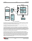
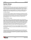
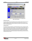
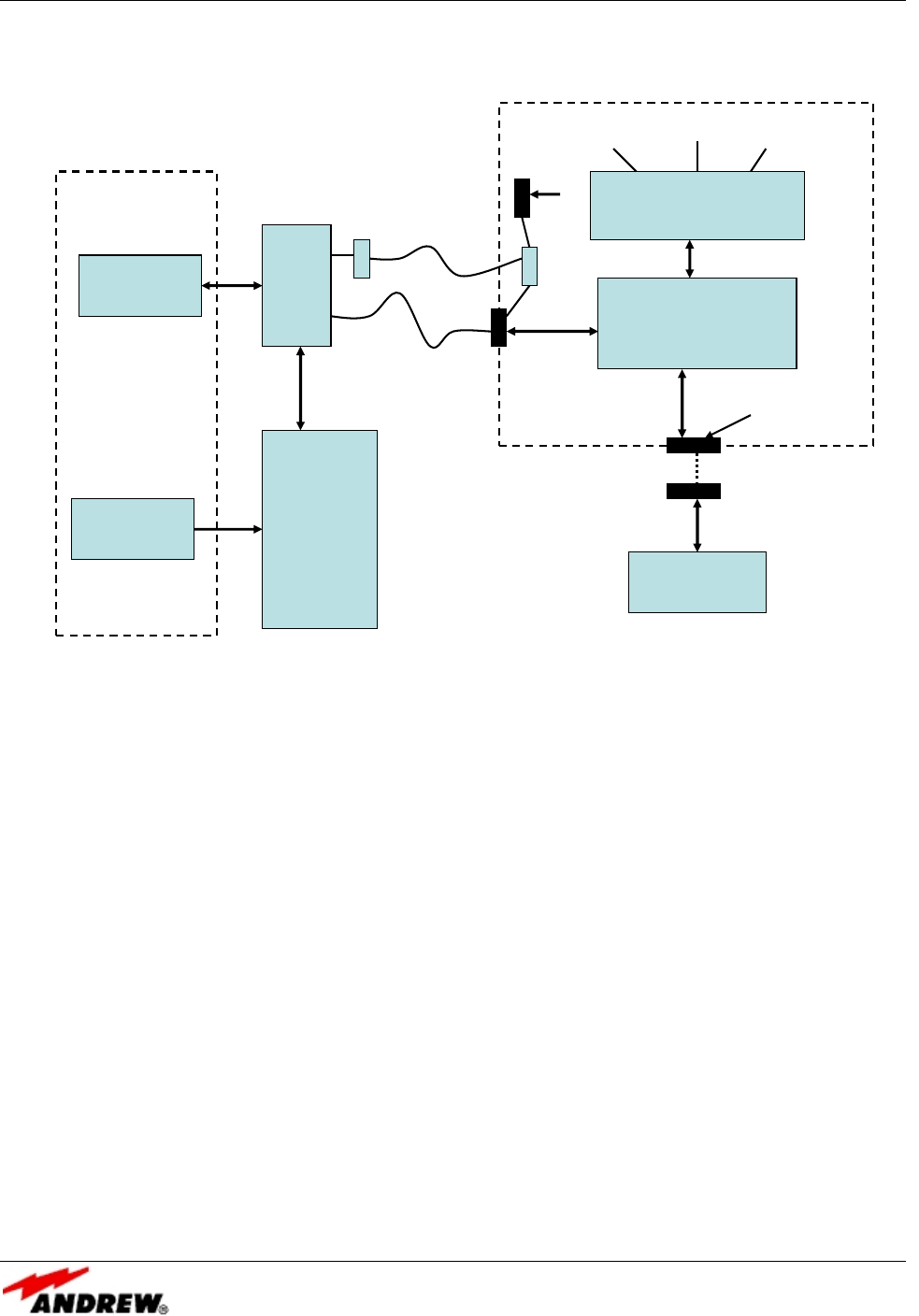
Figure 1: System Diagram
The LMKVS-CPU is the overall manager for the antenna position and satellite signal tracking. The LMKVS-
CPU consists of a Single Board Computer (SBC), a Motor Control Unit (MC-2), Variable Frequency Drives
(VFD) and an Ethernet interface for web browser display and control.
The LMKVS-CPU can also position the antenna via a hand-held unit. Using the handheld unit direction
control buttons, the antenna may be moved in all three axes.
The ACS3000 primary task will be to position the antenna to the received signal of a selected satellite. The
initial setup of the ACS3000 include a full set of all satellites. It builds a subset of those satellites that are
visible to the particular antenna given the antenna latitude and longitude. Using this subset, the operator may
select a specific satellite to point at and may reposition to any of the satellites in the subset at will. In addition
to the primary task, the ACS3000 is able to move to any specified position the operator designates. The
Motor Control Unit will handle the antenna movement rate autonomously once given the coordinates desired
by the operator or as calculated by the SBC during tracking.
The Ethernet connection to the SBC will tie into an Ethernet hub that directly connects to the Beacon
Interface Assembly and browser devices. The Beacon Interface Assembly provides the connection via the
Ethernet hub to the Beacon Receiver data. The data is used to position the antenna on the satellite during
Step Track or SmarTrack® operation The Motor Control Unit connects directly to the VFD's to control the
motors. The Motor Control Unit also connects directly to the limit switches and the resolvers. The MC-2
controls the rate loop used to move the antenna via the hardware and does not need software feedback to
speed up or slow down the movement. The Motor Control Unit communicates with the Single Board
Computer via an internal RS-422 connection.