


11-APR-06 Rev E OMACS3000
30 of 51
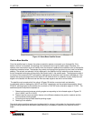
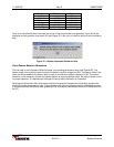
System Screens
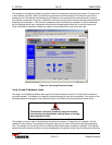
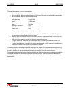
Direction Minimum Maxium
Az East 5 deg 175 deg
Az West 185 deg 355 deg
El Down 0 deg 40 deg
El Up 50 deg 90 deg
Pol CCW 0 deg 89.9 deg
Pol CW 90.1 deg 180.0 deg
Table 2: Software Limits Ranges
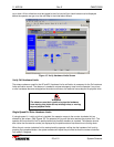
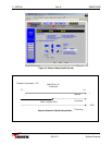
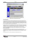
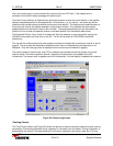
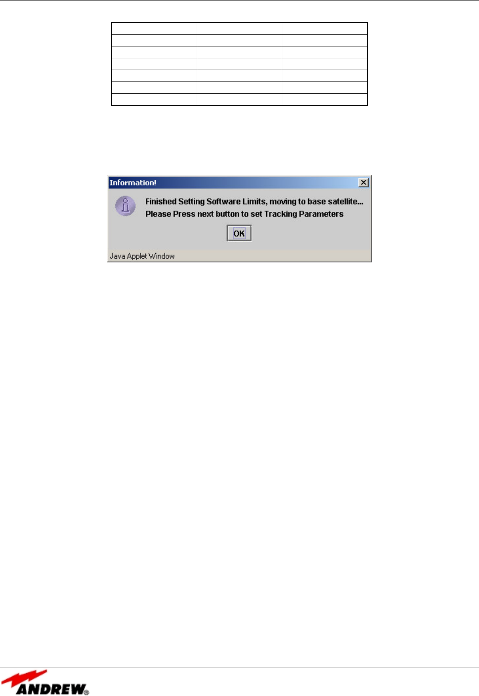
Once all of the software limits have been set and all of the check boxes have appeared, Figure 20 will be
displayed and the operator must select OK (see
Figure 21
), then next, to continue with the next initialization
step.
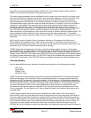
Figure 21: Validate Automated Software Limits
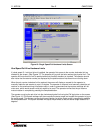
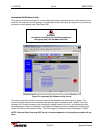
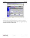
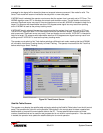
Enter Beacon Receiver Parameters
The final step in the Initialization Wizard process is the tracking parameters setup (see
Figure 22
). The
beacon slope is the multiplier used to convert the beacon receiver voltage into dBs. The beacon offset is the
value that will be added to the beacon data in order to normalize the beacon reading to 0 dB. The beacon
frequency is the frequency at which the satellite beacon is being transmitted. Note: the slope must be correct
for proper operation. It is advised that the slope be verified after initialization is completed.
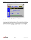
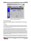
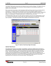
Selecting the Next button after valid values have been entered will complete the initialization process and
save all the setup parameters to a file. Popup windows will notify the operator that the initialization process
is complete and that the satellite table (glblsat.tbl) was successfully downloaded from the ACS3000 server to
the PC.