


11-APR-06 Rev E OMACS3000
7 of 51
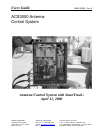
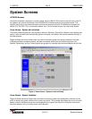
System Description
Indicators Within the LMKVS-CPU
The MC-2 and the Low Temperature Board contain LED's that indicate certain fault and status conditions.
Within the LMKVS-CPU the MC-2 is designated A1 and the Low Temperature Board is designated A5.
MC-2 Description
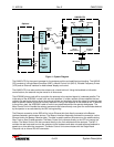
The MC-2 Motor Control Logic Assembly handles feedback from antenna mounted limit switches and
resolvers and provides Variable Frequency Drive (VFD) and motor control for the antenna mounted drive
motors. The MC-2 is a compact card cage based design comprising a motherboard and three vertically
attached daughter cards. Each card including the motherboard provides specific functionality and fault/status
indication. The MC-2 mounts to the LMKVS-CPU main panel by means of four standoffs.
Motherboard Limit/Status Card (LIM-2)
The Motherboard Limit/Status Card handles input power distribution, provides a passive back plane for
daughter cards, and provides for 12 independent limit/status switch inputs. Each limit/status switch input has
an associated LED indicating input logic condition. The LED's are located near the wiring input connectors.
The LIM-2 provides the following indications based on limit/status input conditions:
Indicator Function LED Condition
DS12 Future Illuminated steady RED
DS11 Future Illuminated steady RED
DS10 Maintenance Port Cable Attached Illuminated steady RED
DS9 Handheld Detected Illuminated steady RED
DS8 Low Temperature Warning Active RED LED Extinguished
DS7 Low EL Status Switch Activated Illuminated steady RED
DS6 POL CCW Limit Switch Activated Illuminated steady RED
DS5 POL CW Limit Switch Activated Illuminated steady RED
DS4 EL Down Limit Switch Activated Illuminated steady RED
DS3 EL Up Limit Switch Activated Illuminated steady RED
DS2 AZ West Limit Switch Activated Illuminated steady RED
DS1 AZ East Limit Switch Activated Illuminated steady RED
DS-1 through DS-4 will blink RED simultaneously when the LIM-2 card has lost the Data Terminal Ready
(DTR) signal with the MPU-17. Additionally, DS-5 through DS-12 will blink RED simultaneously after loss of
good data from the MPU-17 for more than 2 seconds.
Microprocessor Card (MPU-17)
The Microprocessor Card (left most card) is 80C188 based and contains a proprietary programmed EPROM
for storage of motor control logic executable code. The MPU-17 communicates with the LKMVS-CPU Single
Board Computer (SBC) by means of a dedicated RS-422 serial interface.
The MPU-17 provides the following status indicators and controls that are viewable from the face of the card:
DS-1 COM FLT Illuminates steady RED after loss of good data from the SBC for more than 2
seconds.
DS-2 LIM FLT Illuminates steady RED upon communication failure with the LIM-2 card and/or
indicates an internal failure of the LIM-2 card.
DS-3 MC FLT Illuminates steady RED upon communication failure with the MD-3 card and/or
indicates an internal failure of the MD-3 card.
DS-4 RES FLT Illuminates steady RED upon communication failure with the RES-2 card and/or
indicates an internal failure of the RES-2 card.