


Step 3
Step 4
37
Installation Procedures
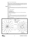
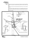
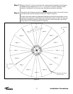
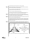
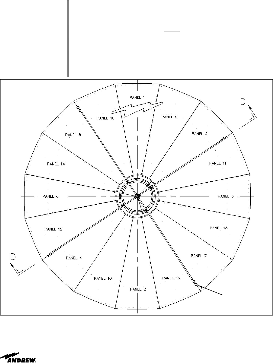
Refer to Figure 23, View A-A and Figure 24. Loosely attach Subreflector Strut Supports
(300089) to panel segements 8-16, 3-11, 7-15 and 4-12 as shown. Replace screws,
washers, lockwashers and nuts previously installed during reflector assembly.
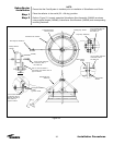
NOTE:
Subreflector Strut Supports should be positioned according to Step 3 and at the 2nd and
3rd seam holes from the outboard end of the rib. Refer to Figure 25.
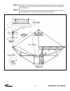
Position and loosely attach pre-assembled Subreflector/Floating Ring assembly to corre-
sponding mounting holes in Subreflector Strut Brackets as shown in Figure 23 using sup-
plied bolts, rectangular washers, lockwashers and nuts. Attach temporary nylon slings,
being careful not to damage subreflector assembly.
Figure 24
Subreflector Strut Support,
300089 (4 Places)
(Figure 25)
(Figure 25)