


Reflector to
Ground Mount
Assembly
Step 1
35
Installation Procedures
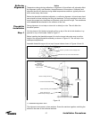
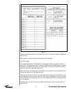
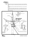
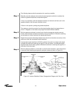
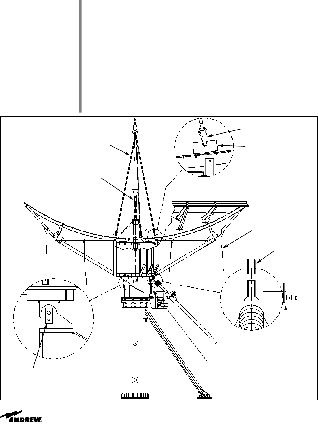
Attach 16ft. (5m) chokers with corresponding 5/8” shackles to the Lifting Tabs (206278).
Attach 30ft. (9m) tag lines of suitable rope equally spaced about reflector (refer to Figure
22).
Note: Ensure ground mount pedestal assembly has elevation jack in the fully retracted
position.
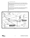
Carefully raise the reflector assembly, position it over the pedestal and gently lower the
assembly onto the pedestal. Attach and tighten using indicated hardware in Figure 22.
Note: After attaching the reflector, the crane may now be removed while the antenna is
in the zenith position.
Figure 22
(Lifting Tab, 206278)
5/8” Shackle
Typical 4 Places)
16ft. (5m) Choker - 4 Straps
Feed System
(Ku Band shown)
Tag Line, 4 places
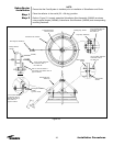
AZ Jack Pin, 302168
3/8”x1.0 Bolt, 9963-632
Lockwasher, 9974-5
Washer, 9997-146
Washer, 9997-188 (2)
Add or remove as needed to
remove excess gap.
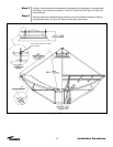
AZ Jack Pin, 302168
3/8”x1.0 Bolt, 9963-632
Lockwasher, 9974-5
Washer, 9997-146
Note: Survival Struts shown here `as installed’ for refer-
ence only. Refer to Operation Section of this manual.