


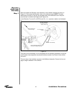
Step 5
23
Installation Procedures
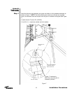
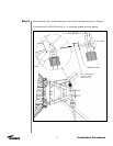
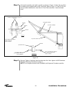
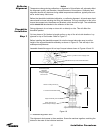
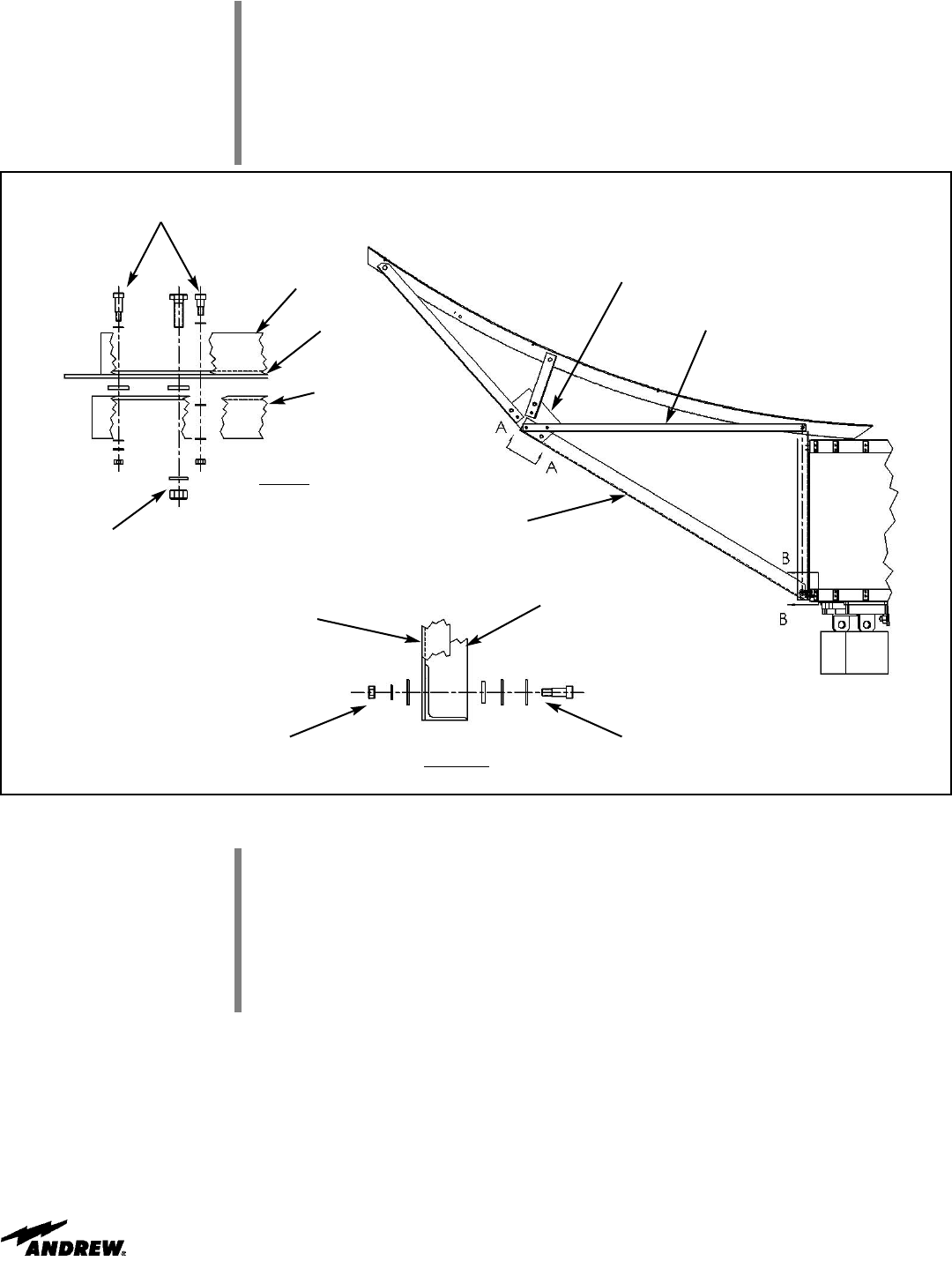
Lift truss/rib assembly and install Long Strut as shown in Figure 14. Note: the Long Strut
is installed on the opposite side of the Truss Plate. Refer to Figure 12, View D-D for pre-
viously installed hardware for Inner Strut to Truss Plate connection. Leave hardware
loose.
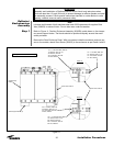
Figure 14
Long Strut, 300076
(Inner Strut, 300080)
(Truss Plate, 300081)
View A-A
Hardware installed at Step 3, Figure 12,
View D-D
5/8”x2.0 Bolt & Nut, 45980-1
Washer, 9997-227
Spacer, 209765-1
Section B-B
5/8”x1.0 Shoulder Bolt, 9858-22
5/8” Washer, 9997-164 (2)
Spacer, 209765-1
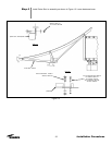
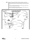
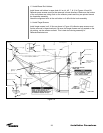
(300076)
(300080)
(300081)
1/2” Washer, 9997-101
1/2” Lockwasher, 9974-64
1/2” Nut, 9999-61
(Enclosure Strut)
(300076)
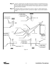
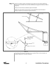
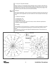
Step 6
Securely Tighten all stainless steel shoulder bolts first. Next, tighten all A325 hardware
following Tensioning Procedure on page 11.
NOTE: Do not tigthen eccentric bolts (300084A) until Alignment Procedure specifies.