


3.5.3 Repeat all 16 adjustments again. This time, after each individual adjustment, fully
tighten seam hardware #24 and 25 on the rib being adjusted.
The outer ring of the reflector is now `locked’ in place.
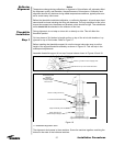
3.6 Fine Inboard Alignment:
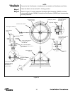
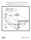
NOTE:
During seam hardware tightening as described in `Fine Inbard Alignment’ take extra pre-
caution not to step on the center of the panels as your weight will displace the panel dur-
ing tightening. Try to step on the directly on the rib/panel connection near the seam hard-
ware.
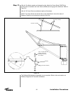
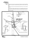
Adjust theodolite elevation angle to the EL2 value. Point and focus the theodolite to tar-
get EL2 located on rib #1. While still focusing to the target, have the inboard cambolt
slowly rotated until the upper edge of the target screw is again within +/-15 sec. (0.0042
deg.) of the theodolite crosshair.
After each individual adjustment, semi-tighten the cambolt nut on the rib being adjusted.
3.6.1 Repeat the procedure described in 3.6 for all 16 inboard target screws at location
EL2.
3.6.2 Repeat all 16 adjustments again. This time, after each individual adjustment, fully
tighten the cambolt nut on the rib being adjusted.
3.6.3 Repeat all 16 adjustments again. This time, after each individual adjustement, fully
tighten seam hardware #23, 22, 21, 20, 19 & 18 on the rib being adjusted.
The inner ring of the reflector is now `locked’ in place.
3.6.4 Repeat all 16 adjustments again at EL2. This time, after each adjustment, fully
tighten seam hardware #17, 16, 15 & 14 on the rib being adjusted.
3.6.5 Repeat all 16 adjustments again at EL2. This time, after each individual adjust-
ment, fully tighten remaining seam hardware (#1 through #13) on the rib being adjusted.
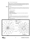
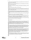
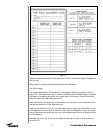
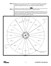
4.0 Data Recording:
After all seam hardware is tight. Re-sight all 16 outboard and all 16 inboard targets and
record their actual final elevation angles. Use the data table provided in Figure 21.
If necessary, this data will be useful for further analysis.
5.0 Theodolite Removal
Remove theodolite assembly from torque tube and properly place components in the
case. Remove all target screws and replace them with proper seam hardware.
Remove all rod holders and replace them with proper seam hardware. Remove tempo-
rary platform.
The reflector is now ready to accept the subreflector struts and be lifted onto the mount.
34
Installation Procedures