


32
Installation Procedures
Step 3
Reflector
Alignment
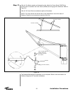
Relocate the stick to rib #7. Focus and adjust the elevation to align to stick scribe line.
Reord as H3.
The specification for height requires that H1, H2 & H3 be within +/-15 seconds (0.0042
degrees) of 90 degrees. This can only be achieved through successive leveling/center-
ing sequences.
Repeat as Necessary:
Repeat 2.2, 2.3, and 2.4 until the calibration specifications are achieved. Each succes-
sive loop through these procedures should produce smaller deviations from the specifi-
cations until they are finally achieved.
After all calibration specifications are achieved, gently tighten the X-Y stage locking screws.
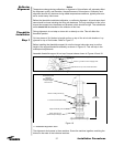
1. lntroduction:
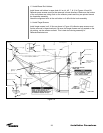
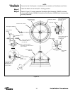
The reflector consists of 16 panels supported by 16 ribs. Each rib is supported and set
in place by a truss assembly. Each truss assembly has two cambolt adjustments which
are used with the theodolite to position the ribs in their theoretical location.
Note:
Complete and proper installation and calibration of the theodolite assembly is required
before proceeding with reflector alignment.
2. Pre-Adjustment Procedure:
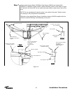
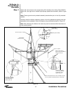
2.1. After the antenna assembly, make sure that all the inboard and outboard cambolts
are set to their maximum upper limit. This is accomplished by turning the cambolt until
the mark on head of the hex bolt is pointing toward the rib, along the axis of the angle
strut (see Figure 19, View `C’).
2.2. Make sure that the nuts retaining the cambolts are not too loose. As a rule of
thumb, tighten the cambolt nut until tight and undo 1/4 turn until the cambolt turns freely
but not totally loose.
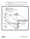
2.3. Before starting alignment, make sure that all the noted hardware associated with
the truss assembly is fully tightened. Refer to Figure 19.
2.4 If not yet done, install special target screws at all locations as indicated in Figure 19). Ensure
that the screw is fully seated on the rib surface. This is best done during reflector assembly.
2.5. Do not put pressure on the torque tube or support struts when sighting through the
theodolite.
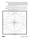
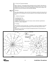
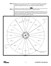
3.0 Rib Alignment (Refer to Figure 19):
3.1 The adjustment sequence of the ribs must be followed in order to achieve proper
alignment. Deviation from the described sequences and procedures will result in more
difficult alignment of the ribs and may even result in an incorrect adjustment of the
reflector itself.
3.2 Refer to Figure 19. Each rib has two target screws which will be used for panel
adjustment. One target screw is located near the outboard cambolt location at seam
hole #27. The other target screw is located near the inboard cambolt location at seam
hole #20.