


Subreflector
Centering
Step 7
Subreflector
Focusing
Step 8
Step 9
39
Installation Procedures
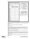
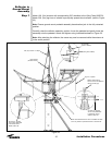
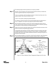
Measure and note the distance between outermost subreflector strut support bolt head
and the subreflector rim as shown in Figure 25. Obtain corresponding measurements
from remaining subreflector struts. These measurements should have a maximum differ-
ential of 0.062 in. (1.5mm). If adjustment is necessary, loosen the four floating ring bolts
and slide subreflector appropriately to achieve the 0.062 in. (1.5mm) differential. Make
sure to re-tighten bolts when finished.
Refer to Figure 25. Use measuring tape to set indicated dimension between bottom edge
of panel and subreflector aperature rim at the three subreflector adjustment stud loca-
tions. Use subreflector adjustment stud hardware to achieve equal axial dimension of
108.75 in. (2762.3mm) at all three locations. Securely tighten adjustment hardware.
Repeat procedure described in Step 7. If any dimensional variation is found, repeat
adjustment procedure described in Step 7 then repeat procedure in Step 8 if required.