


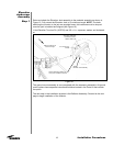
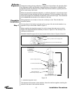
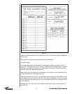
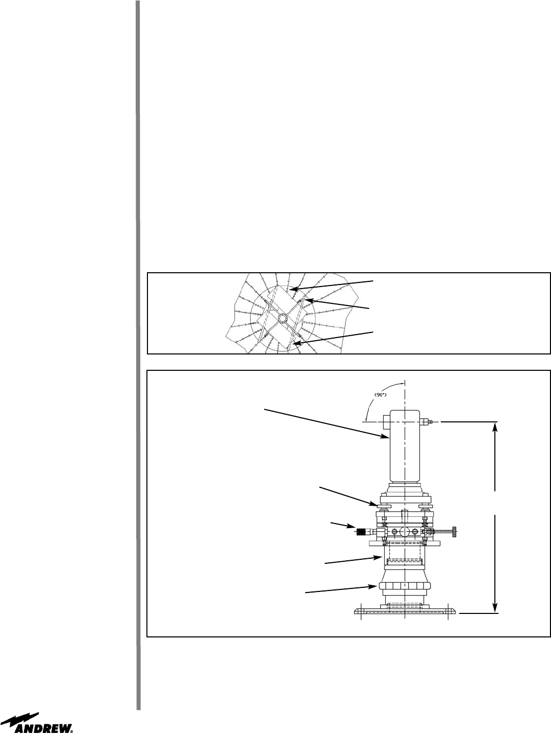
Customer-Supplied
Theodolite
Wild Heerbrugg T2
or TopCon Digital
DT-05 or 05A
X-Y Dual Axis Translation Stage
Rotary Precision Lift
(Rotate to Adjust Height)
18.050”
(458.47mm)
Support Assembly, 223712
Reflector
Alignment
Theodolite
Installation
Step 1
Notice
Temperature change during calibration or alignment of this reflector will adversely effect
the alignment quality, and therefore, the performance of this antenna. Calibration and
alignment should only be done during stable temperature conditions, typically after sun-
set or under heavy cloud cover.
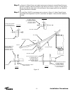
Before the theodolite installation/calibration, or rerflector alignment, all panel seam hard-
ware should be loose including the lifting tab hardware. The only exception to this is the
torque tube support strut hardware and brackets, which should be tight. The subreflector
struts should not be attached to the reflector at this time.
During alignment, do not step on drum skin or directly on ribs. This will affect the
theodolite position.
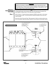
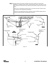
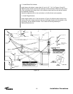
Cut two pieces of 2x4 lumber to length and lay on top of ribs at hub tab locations. Lay
plywood on top of 2x4 lumber. Refer to Figure 17.
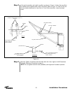
Before installing the theodolite support kit onto the torque tube make sure to set the
height of the support/theodolite assembly as shown in Figure 18. This will help in the
subsequent adjustments.
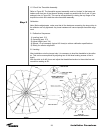
Assemble theodolite support kit on top of torque tube as shown in Figures 18 and 19.
27
Installation Procedures
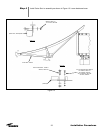
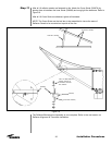
1.2 Assemble Alignment Stick:
The alignment stick comes in three sections. Screw the sections together, matching the
letters on the ends of the individual sections.
Tribach Leveling Screws (3)
Figure 18
Figure 17
2x 1/2” thk. x 18”x55” plywood
2x4x70” lg. lumber cut from shipping crate
Set 2x4 on top of rib at hub tab location