


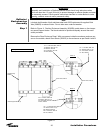
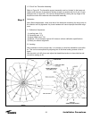
Step 7
24
Installation Procedures
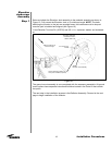
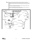
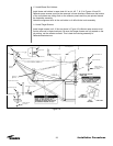
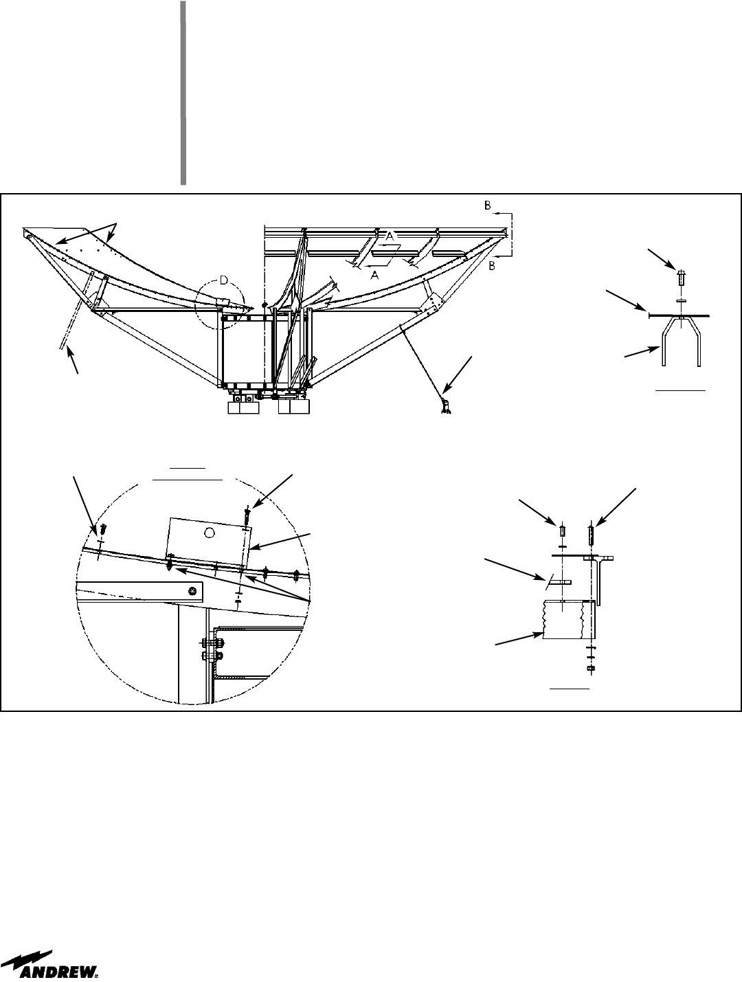
Attach stretch-formed Skirts (222765-2), Strip Spacer (300040) and Inboard Skirt
(300082-2) to Reflector Panels (222677) before attaching panels to ribs. Refer to Figure
15, Section A-A & View B-B. Do not install outer-most screw on each side of skirt at this
time.
NOTE: Do not overtighten skirt panel screws. It may deform the panel. Tighten screws
only enough to fully compress the lockwashers.
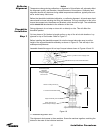
Referring to the supplied Feed Support Installation drawing (240159) supplied with the
antenna, install the Rotating Tube Assembly at this point.
Figure 15
Section A-A
5/16”x3/4 Screw, 209236
5/16” Lockwasher
Panel, 222677
Inboard Skirt,
300082-2
View B-B
5/16”x1-1/2 Screw, 9959-11
Nut, 9999-59
Lockwasher, 9974-17
Washer, 9997-74
5/16”x3/4 Screw, 209236
Lockwasher, 9974-17
Strip Spacer, 300040
Skirt, 222765-2
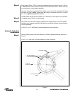
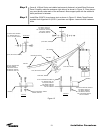
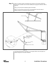
Tag Line & Stake,
4 Places
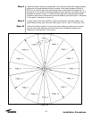
Install these seam bolts first
(4th hole from edge)
2”x4” (50x100mm)
Temporary wood support,
4 places
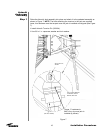
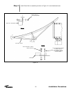
1/4”x1-1/4” Bolt, 9963-76
Washer, 9997-131 (2)
Nut, 9999-57
Typical 4 Places
View `D’
Typical 4 Places
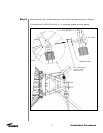
Lifting Tab, 206278
5/16”x3/4 Screw, 209236
Lockwasher, 9974-17
8th & 10th hardware loca-
tions