


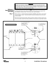
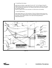
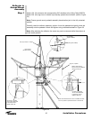
1.3 Install Brass Rod Holders:
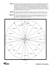
Install brass rod holders in seam hole #11 on rib #2, 7, & 10 in Figures 19 and 20.
Reflector seam screws must first be removed in these locations. Make sure the bottom
of the rod holders are sitting flush on the reflector panels and they are pointed toward
the theodolite assembly.
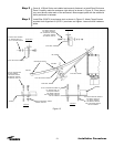
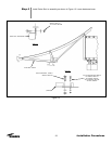
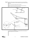
Attach the alignment stick to the rod holder in rib #2 with the knob assembly.
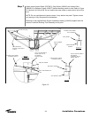
1.4 Install Target Screws:
Install target screws in all 16 ribs as shown in Figure 19 (reflector seam screws must
first be removed in these locations). Be sure that target screws are fully seated on the
rib surface, not the reflector surface. This is best done during assembly of
Reflector/Backstructure.
28
Installation Procedures
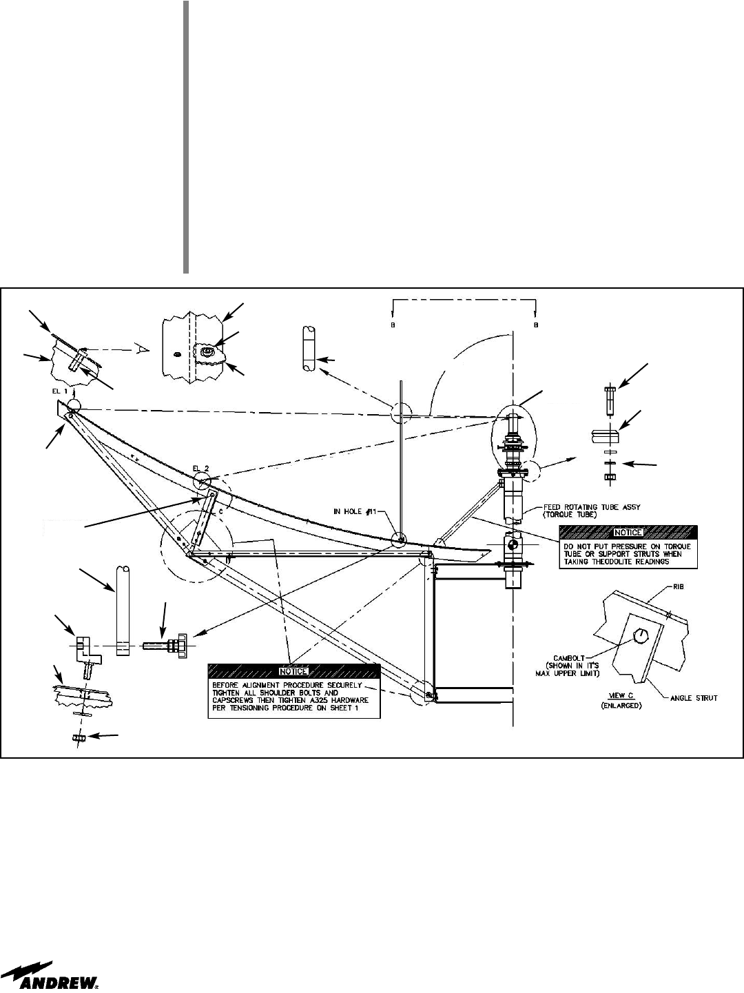
Figure 19
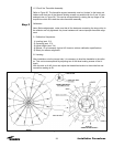
EL1= 88
o
55’ 23” (88.9231
o
), Hole #27
EL2= 101
o
23’ 28” (101.3911
o
), Hole #20
(Rib)
Theodolite Height Line
Alignment Stick, 223721A
1/2”x2.0 Bolt, 9963.149
90
o
0’0”
(Support Assembly)
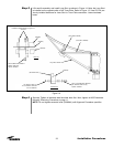
Washer, 9997-42
Nut, 9999-57
Refer to Figure 20
Knob Assembly, 223745A
Rod Holder, 223718A
Rib/Reflector Panel
Washer, 9997-57
Lockwasher, 9974-64
Nut, 9999-61
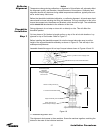
Cambolt 1
(outboard)
Cambolt 2
(inboard)
Target Screw
(Panel Skin)
Target Screw, 223717
(Panel Skin)
(Rib)
Figure 18