


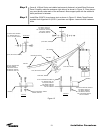
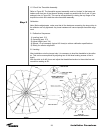

Step 2
1.5 “Clock" the Theodolite Assembly:
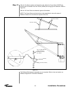
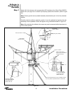
Refer to Figure 20. The theodolite support assembly must be 'clocked' to the brass rod
holders such that two of the tribrach leveling screws run parallel with ribs 2 and 10 (see
enlarged view in Figure 20). This can be accomplished by rotating the top flange of the
torque tube which will rotate the entire theodolite assembly.
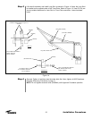
Calibration:
Note: Before adjustments, make sure that all the hardware connecting the torque tube to
the reflector are fully tightened. Any loose hardware will cause improper theodolite align-
ment.
2.1 Calibration Sequences:
1) Leveling (sect. 2.2)
2) Centering (sect. 2.3)
3) Adjust Height (sect. 2.4)
4) Repeat 1-3 as necessary (typical 4-5 times) to achieve calibration specifications.
5) Ready for reflector alignment.
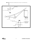
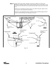
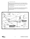
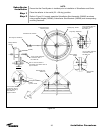
2.2 Leveling:
After installation onto the torque tube, it is necessary to level the theodolite to the reflec-
tor. This can be accomplished by adjusting two of the three leveling screws of the tri-
brach.
With the stick at rib #2, focus and adjust the theodolite elevation to the scribe line and
record this reading as R1.
29
Installation Procedures
Figure 20