


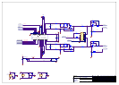
AV8 Power Supply Board
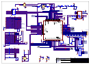
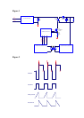
The 40W Resonant supply is designed to produce
extremely low levels of conducted and radiated noise. The
supply is based around a discontinuous inductor current
single ended flyback topology with active clamp. The
active clamp eliminates the power losses normally
associated with RCD type clamps and also eliminates the
high voltage ringing waveform normally present on the
primary inductance. In addition current is transferred to the
output capacitors as a half wave sinusoid rather than a
triangle wave which would normally be expected from a
flyback supply. The sinusoidal current waveform into the
output capacitors results in reduced output noise with
attenuated high frequency response.
The PSU provides the following functionality
! Universal input voltage range 85V ac rms to
265V ac rms.
! Eight regulated supply rails.
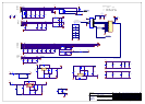
The output voltages are provided as 3 groups of supplies.
! Digital supplies
The digital supplies are for use on non audio circuits e.g
microprocessor and similar circuitry, they are referenced to
DGND.
! Analogue supplies
The analogue supplies are for use on audio circuitry, they
are referenced to AGND.
Note. The rated supply currents for the analogue supplies
are 300mA per rail. The +18V and –18V supplies are
provided by 3 terminal regulators which derive their
current from the +21V and –21V rails. The current ratings
can thus be written.
Sum of output current from +21V and +18V = 0.3A max
Sum of output current from -21V and -18V = 0.3A max
AGND and DGND are joined together at 1 place on the
PSU (LK1)
! Adjustable supplies
o +40V (adjustable)
o +7V5 (adjustable))
These supplies are floating to allow them to be configured
as positive or negative supplies to suit the particular
display used.
The outputs are semi-regulated by a zener/emitter follower
circuit. The Output voltages my be trimmed by addition of
resistors between the lines +40V_SET and +5V_SET.
Note. The +40V rail was originally to be set to +36V as
marked on the drawings but it was found that the display
was to bright and subsequently has been adjusted to +21V.
External Synchronisation Input
The free running frequency of the PSU is around 75KHz.
For applications which require synchronisation to a system
clock, the PSU may be entrained to an applied Sync signal.
The Sync signal should be between 85KHz and 100KHz.
The Sync signal is applied via line SYNC (SK8-1) and
should be a TTL level 50%duty cycle square wave.
External PSU Kill Signal
For applications which require a means of shutting down
the PSU (e.g. in the event of a detected fault scenario) then
PSU latched shutdown may be initiated by pulling and
holding line PSUKILL* to DGND. The PSU will enter a
latched shutdown state after around 1second. The Latched
shutdown forces all output supplies to 0V and can be
defeated only by removing the mains input to the PSU for
>15seconds.
Under-voltage lockout
The PSU is protected against the input voltage being too
low (which would otherwise cause the input current to be
excessive for a given output power). In the event of the
input voltage being <75V ac rms then the PSU control IC
will disable gate drive signals and the PSU output voltages
will fall to zero.
Output Over-voltage Protection
The output voltages are monitored and in the event of the
output voltages rising approx 15% above specified limits
for >0.5 seconds then a latched shutdown event will be
triggered. This mechanism is not intended to protect
sensitive components from damaging transients but is
intended to protect the PSU and its load in the event of the
feedback signal failure.
In this design both the 3V3 and +5V are sensed. In the
event of a failure in e.g. the 5V rail then the feedback loop
will try to make the other rail voltage high enough to
supply all of the feedback current which the other, now
broken, supply was formerly contributing toward. This
would normally force the 3V3 supply to more than twice
its expected value (and all of the other supplies would be
multiplied by the same factor). The provided mechanism
prevents this eventuality.
Feedback loop failure protection
In the event of the feedback loop failing (eg. due to a
broken feedback component) then the supply will enter
latched shutdown after around 1 second.
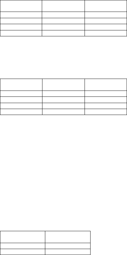
Digital supply
rails
Voltage tolerance Max current
+3V3 3% 1.5A
+5V 3% 1A
+12V 12.9V 5% 500mA
-12V 12.9V 5% 500mA
Analogue supply
rails
Voltage tolerance Max current
+20.8V 5% 300mA
-20.8V 5% 300mA
+18V 2% 300mA
-18V 2% 300mA
Adjustable supply
rails
Max current
+21V 30mA
5V 150mA