


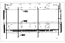
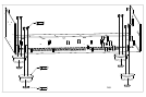
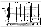
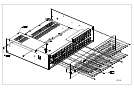
8. Fit the video board (L922AY – main board) to the
chassis (do not fit rear panel yet). Ensure the board is pushed to
the back of the chassis before tightening down the board. Use
the H041 pillars in the two holes closest to the S-video
connectors (right hand side nearest the EMC screen as viewed
from the connector side). See FIG6.
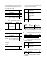
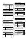
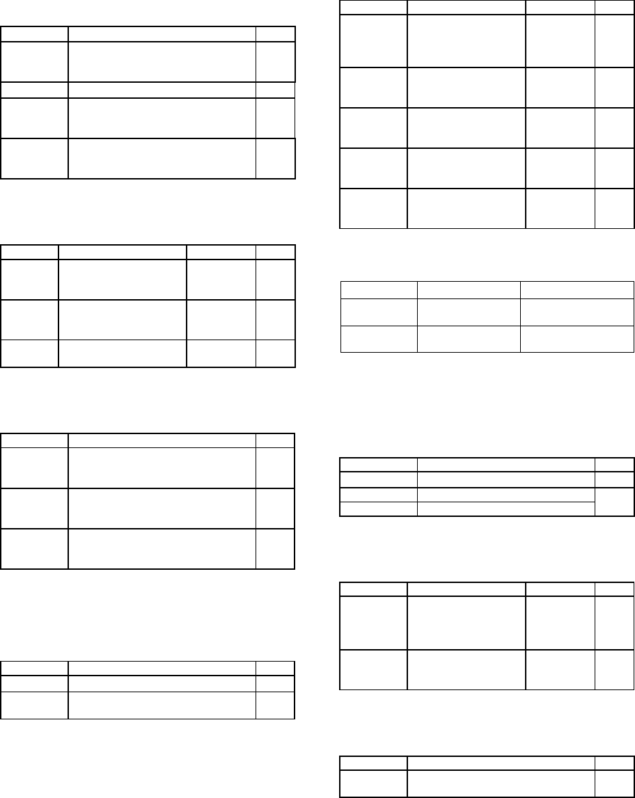
Part No. Description Qty
HF4V09B Screw Self-Tapping-SEMS No4x9mm
Pan Torx-Slot Steel Zinc-Plate Black
(into EMC shield)
2
H041 22 mf pillars 2
HA3V06A Screw Machine M3x6mm Pan Torx
Steel Zinc-Plate Clear thro’ video PCB
into standoffs
9
HF4V09B Screw Self-Tapping-SEMS No4x9mm
Pan Torx-Slot Steel Zinc-Plate Black
(thro’ RP into sockets)
9
Once the video board is in place, fit the following
cables to the video board:
Part No. Description Reference Qty
L922CA 22-way foil cable from
top video to video
100mm
SK700 1
L925CA 8-way AMP CT from
video to horiz power
280mm
SK1000 1
L931CA 30-way foil cable from
digital to video 190mm
SK702 1
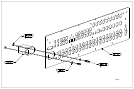
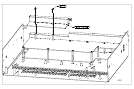
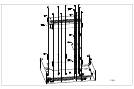
9. Fit the top video board (L922AY – sub board) to
chassis (do not fit rear panel). See FIG7.
Part No. Description Qty
HF4V09B Screw Self-Tapping-SEMS No4x9mm
Pan Torx-Slot Steel Zinc-Plate Black
(into EMC shield)
1
HA3V06A Screw Machine M3x6mm Pan Torx
Steel Zinc-Plate Clear through top
video PCB into standoffs
2
HF4V09B Screw Self-Tapping-SEMS No4x9mm
Pan Torx-Slot Steel Zinc-Plate Black
(thro’ RP into sockets)
9
Connect L922CA from the video board (SK700) to the top-video
board (SK209)
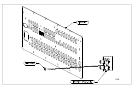
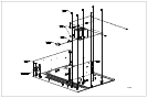
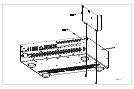
10. Fit the power can using 2x HA3V06A into standoffs.
See FIG8.
Part No. Description Qty
E876MC Power Can 1
HA3V06A Screw Machine M3x6mm Pan Torx
Steel Zinc-Plate Clear into standoffs
2
11. Fit the horizontal power PCB (L897AY – snap-off
part 2) using 6x HA3V06A screws into standoffs. Refer to FIG8.
Once the pcb is in place, fit the cables below.
Part No. Description Reference Qty
HA3V06A Screw Machine
M3x6mm Pan Torx
Steel Zinc-Plate Clear
into standoffs
6
L925CA 8-way AMP CT from
horiz power to digital
280mm
SK5 1
L926CA 7-way AMP CT from
horiz power to digital
350mm
SK7 1
L928CA 6-way AMP CT from
horiz power to digital
540mm
SK2 1
L925CA 8-way AMP CT from
horiz power to phase
lock loop 280mm
SK4 1
Connect the following cables using the reference table below:
Part No. From To
L927CA Audio / SK801 Horizontal power /
SK3
L925CA Video / SK1000 Horizontal power /
SK5
N.B. The Video cable L925CA has an excess of length so that the
video board may be removed but still remain connected when the
unit is serviced. A cable tie should be used to hold this excess
when the board is installed.
12. Fit the mains power button to the power switch, with
the button to the top. Refer to FIG8.
Part No. Description Qty
E887PM DiVA power button adapter 1
E850PM FMJ mains button (silver)
E850PMB FMJ mains button (black)
1
13. Fit the vertical power PCB. Once the pcb is in place,
fit the cable specified below.
Part No. Description Reference Qty
HA3V06A Screw Machine
M3x6mm Pan Torx
Steel Zinc-Plate Clear
into standoffs
2
L929CA 4-way AMP CT from
digital to vertical
power 220mm
SK8 1
14. Fit the headphone PCB (snap-off from video board).
Fit with socket facing to the front. Refer to FIG8.
Part No. Description Qty
HA3V06A Screw Machine M3x6mm Pan Torx
Steel Zinc-Plate Clear into standoffs
2
Connect L930CA from audio board (SK917) to the headphone
board (SKP1).