


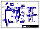
means that when the output of the OSD is switched into
the output the DC level does not change avoiding any
flickering or brightness changes.
The Y output is clamped to 0v at its sync tip by the
transistor Q301. This is an active clamp that pulls the DC
level to 0v every time a sync pulse occurs. The clamp
signal is created from the composite sync stripped by the
OSD chip IC302 this is the shortened to a ~700nS pulse by
the mono stable IC308. The time of the pulse created by
IC308 is set by R310 and C304. The clamp signal is also
used to clamp the incoming Y signal of both S video and
YUV signals. It is also used when the system is running in
RGB mode to clamp the RGB signals to black level.
The RGB output is used when the system is operating in
RGB mode and creates the colour information for the text
being inserted. The level is reduced from TTL levels to
video levels by the potential dividers that feed into video
buffers made from the opamps IC300 and IC303. A sync
signal can be added to the green output by activating the
output of the AND gate IC502. This raises the DC level of
the whole signal by 300mV then introduces 300mV syncs
to 0V.
The PAL and NTSC clocks are generated by the CMOS
oscillators. The oscillator is made by applying feedback
around un-buffered 74HCU04 inverters. The oscillation is
then buffered and amplified by some of the extra gates left
in the 74HCU04 pack. Both oscillators run at all times so
that the system can cope if Zone 1 is running NTSC and
Zone 2 is running PAL. Which clock is used for the zone 1
and zone 2 OSD chips is controlled by the Tri-state buffers
in IC305, these form a low noise 2:1 mux for the clocks.
RC5 I/O Triggers and RS232
Refer to circuit diagram L922 sheet 5
Sheet 5 has two RC5 demodulators made using IC400 and
IC401, one RC5 mixer and buffer, two 100mA current
limited trigger outputs, the RS232 output connector and
the program button for reprogramming the Flash memory
in the micro controller.
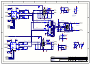
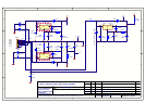
YUV/RGB Video Mux and OSD insert
Refer to circuit diagram L922 sheet 6
The circuit on this sheet multiplexes between the three
RGB/YUV inputs using the high speed multiplexers IC503
and IC505. Once the signal has been selected it is AC
coupled and DC restored using the active clamps
Q511,Q500 and Q512. (operation of this clamp is
described on sheet 4). The multiplexer following the DC
restore IC506 inserts text using the fast blanking signal
from the OSD chip. IC506 has a gain of 2 and 75R output
capability to drive the output directly.
The type of signal that is inserted (RGB or YUV) is
selected by the mux chip IC500A. The mux can select the
signals from the RGB buffers on Sheet 4 for RGB
operation or the Y output of the OSD chip and DC levels
generated by the potential divider R519, R500 and
R520,R522. These DC levels generate a blue background
for the text when it is not being overlaid on the incoming
video. IC501 switches between the blue background levels
and zero volts the signal CHAR OUT is active when a
character is present on the output and it is this that
switches IC501. The OSD B and OSD G signals are In a
logical AND with the Char Out signal to switch between
blue & white colour. When the circuit is set to blue output,
no green output & no char the colour is set to blue i.e it is
back ground.
In any other condition the colour is set to white because it
is a character i.e text is being displayed.
Zero volts is used when inserting characters as this
provides a colourless background. I.e. the characters are
white on a blue background.
Q503, Q504 and Q505 are used to mute the RGB output of
the unit when it is not in use and at power up.
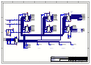
SPDIF MUX and RXTX
Refer to circuit diagram L922 sheet 7
The circuit on this sheet multiplexes the seven SPDIF
inputs to a single line that is buffered and passed to the
digital pcb.
The input signals are 75 R terminated then AC coupled
into the multiplexer. The multiplexer is made up of The
2:1 CMOS switches IC600 IC601 and IC602. The
multiplexer works in the same way as the audio
multiplexers. It switches the signal between the input to
the buffer circuit and a DC level at half the rail i.e. 2.5V.
Each multiplexer has a independent select line, only one
multiplexer should be selected at a time as the circuit will
mix the signal together if more than one is selected.
After the input signal has been selected by the mux it is
buffered and amplified by IC603. Applying feedback
around a 74HCU04 biases it into the linear region. The
three stages amplify the 0.5V P-P SPDIF signal up to a 5V
logic level. Two outputs are buffered off of this logic
level, one to go to the digital board the other is used for the
digital record loop.
The digital record output is driven by IC605 either the
buffered output of the input mux or the SPDIF output of
the DSP (from the ADC input) can be selected. The signal
is select by the lines SPDIF LOOP and SPDIF ADC TX.
The 75R characteristic impedance is formed from the
parallel combination of R613 100R, R626 680R and R627
680R. The digital output is AC coupled.
Control of all of the select lines for the Multiplexers and
Buffers is handled by IC604 and IC606. IC604 and IC606
are latched serial to parallel converters.
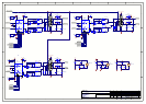
SVIDEO and CVBS OSD insert
Refer to circuit diagram L922 sheet 8
The circuits on this sheet switch the OSD generated test
into the incoming video. IC700 is the fast video switch that
inserts the text, it is controlled by the fast banking signal
directly out of the OSD chip. IC700 has a gain of 2 and
can drive 75R loads.
The composite video signal is sync tip clamped at the
input to the switch by Q701 and Q705 this works in the
same way as the Sync tip clamp on sheet 4 that operates on
the composite signal out of the OSD chip. These two sync
tip clamps ensure that the DC level is the same at the input
to the switch so that the text is switched in at the correct
DC level.
The S-video Y input is actively clamped by the clamp
signal as described on sheet 4. This ensures that the two S-
video Y inputs, one from the input source and the other
from OSD, are at the same DC level. Ensuring the DC
levels are correct means the text can be inserted at the
correct level.