


Input switching
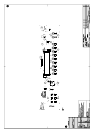
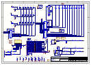
Refer to circuit diagram L921 sheet 1
The 24 off 74HCT4053 analogue multiplexers route the
various analogue inputs to the four output mix buses:-
! VCR
! Tape
! Analogue
! Zone2
The main stereo inputs have 100pF NP0 capacitors to
ground to reduce any high frequency signals radiating
from the input cables which are connected to the unit.
This is an EMC preventative measure.
In addition to be able to select any particular input as the
source, the input impedance of each input connector was
required to remain constant regardless of whether it was
selected or not. Input selection is therefore performed
using a method called “virtual earth mixing”. Each input
can be switched to one of the four stereo busses via an
input resistor, or switched to ground
For simplicity consider only the main ANALOGUE L
MIX bus. Each input is fed onto the common bus via a
resistor and an electronic switch. The bus is the input to
an op-amp in an inverting configuration. The switch either
allows the signal through to the op-amp, or shunts it to
ground. The inverting input of an inverting configured op-
amp effectively behaves as a ground (hence “virtual
earth”), which is why the input impedance looks the same
regardless of the state of the switch.
In theory all inputs can mix into the op-amp
simultaneously, but the control software only allows one
input switch to connect to the op-amp at a time. If
multiple inputs can be heard simultaneously then there
may be a problem with the control logic (see L921 circuit
sheet 7), or the AUD SDATA line from the Digital board
may be latched high.
For the “ANALOGUE L MIX” and “ANALOGUE R
MIX” buses, the resistor is 15kΩ, for the other three buses,
the value is 100kΩ. The three 100kΩ in parallel with
15kΩ give a total input impedance of just over 10kΩ - the
minimum required for THX certification. These particular
values were chosen to maximise the noise performance of
the main stereo ANALOGUE L/R MIX buses, bearing in
mind that a larger value resistor has poorer noise
performance. The 100kΩ resistors feed into the op-amps
of the less critical audio paths for ZONE2 and the record
loops VCR MIX and TAPE MIX.
Input gain range
Refer to circuit diagram L921 sheet 3
The gain ranger sets the headroom for the A-D converter
(on the digital board) and for the rest of the analogue
chain. The aim is to set the gain such that clip is not quite
reached with the input of the unit receiving a maximum
signal. Excessive headroom reduces signal-to-noise
performance unnecessarily. Left and right channels are
identical, therefore only the left channel will be described.
IC301A is the op-amp into which the input resistors feed
(described in Input switching above). R302 in the fixed
feedback path ensures the op-amp cannot go open loop,
causing it to latch into a power rail. C301 compensates for
small stray capacitances at the op-amp input, ensuring it
does not oscillate. Switching in R303, R304, R305 or any
combination in parallel with R302 sets the closed loop
gain with reference to the 15kΩ input resistor. IC302
selects which of the three resistors are in circuit. It is
controlled by the micro via control line demultiplexer
IC707. Several ranges, nominally +6dB, 0dB, -6dB and -
12dB can be generated depending on the state of the
‘GAIN RANGE’ lines A,B & C as shown below.
Gain Range +6dB 0dB -6dB -12dB
A LOW HI HI HI
B LOW LOW HI HI
C LOW LOW LOW HI
IC301A output feeds into an inverting unity gain buffer
(IC301B) which is referenced to 0V_SIG. R315 links
0V_SIG to the ADC circuits on the digital board via
connector SK915.
External / internal multichannel & main
stereo input multiplexer
Refer to circuit diagram L921 sheet 2
This group of multiplexers selects the signals to be routed
to the output volume controls.
The three signal sources are:-
! FROM MAIN GR(L/R)
stereo from the gain ranger
! FROM INT MAIN(L/R)
multichannel from the digital-analogue
converters on the digital board
! FROM EXT MAIN(L/R)
external analogue multichannel source
These are selected by one of three control lines from the
micro via control line demultiplexer IC707.
! ANALOGUE TO MAIN
! INT DECODER
! EXT DECODER
The multiplexers (except for IC204) select the feed-
forward resistor in a unity gain inverting amplifier. Left
and right sub-circuits are identical, therefore only left
(IC201, IC203A) will be described.
When ANALOGUE TO MAIN is high, the signal from the
gain ranger is selected via R201. The feedback around op-
amp IC203A is more complex than a standard inverting
configuration. Capacitor C203 removes any dc content to
subsequent circuits. However, since capacitors have non-
linear characteristics which are undesirable and adversely
affect the sound, C203 is placed in the feedback path in
series with the feedback resistor R205 to compensate for
these errors. R204 is in parallel with C203 and R205 to
provide a local dc feedback path. Without this the op-amp
would be open-loop at dc and would therefore latch into
the power rail. C202 compensates for stray capacitance at
the input of the op-amp and rolls off very high frequency
gain to provide stability.
It is normal to see a few volts of dc offset at the output pin
of the op-amp. This is because of the high dc gain of the
circuit (1M / 15k ≈ 67 or +36.5dB). This dc offset could
be due to the input offset voltage of the op-amps
themselves (up to ±2mV for OPA2134, producing a dc
offset at the output of 134mV) or because of a dc offset
supplied by the signal source connected to the unit. In the
normal operating mode where the gain ranger is at unity,
the absolute maximum permitted dc offset at the input to
the unit is approximately 150mV. This would produce a
dc offset at the output pin of the op-amp of about 10.2V.
This would still leave sufficient headroom for a 2Vrms
audio signal on top of this offset.