


AV8 Phono Board
Circuit Description
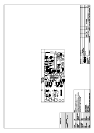
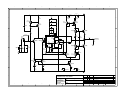
Refer to circuit diagram L870 sheet 1
The phono board is a simple single stage RIAA amplifier
and consists of two channels of high gain amplification,
and the ability to switch between moving magnet (MM)
and moving coil (MC) settings.
PSU
The unit derives its +
15V regulated rails from the unit it is
fitted into with only local decoupling capacitors on board.
Interface
The unit connects to the host unit via a 8 way connector.
Amplification
The left channel has designators beginning with 100, and
the right with 200. For the purposes of this description the
left channel will be described, as the right channel is the
same in all respects.
The amplifier is a small signal class A voltage feedback
amplifier with switch able gain. The input consists of an
actively loaded differential pair of very low noise PNP
transistors (TR106, TR107). These transistors are very
specific and should only be replaced with identical parts
with the E grade high gain. TR100 and TR101 form a
current source for the pair, which sets the quiescent current
for the entire amplifier. The active load consists of TR110
and TR111, which forms part of the differential current
mirror with TR112, TR113 & TR114. This differential
stage also has an active load (TR102 & TR103) to keep
gain to a maximum.
Both of these differential stages are designed to have as
much gain as possible to enable the single stage design.
The RIAA response is achieved in the feedback network:
C101, C110, C111, C112, C119, C120 and R115, R112.
C115 is used to correct between MM and MC gains as the
amplifier is non-inverting.
SW100 switches between MM and MC. Two poles of the
switch change between the different loading required for
each type of the cartridge: R108 & C109 for MM and
added in parallel for MC R104 & C108. The other two
poles change the feedback resister value to alter the gain:
R105 for MM and added in parallel for MC R123.
The DC offset is controlled by a non-inverting servo built
around IC100. The amount of servo current is different for
each gain setting via R111 (MM) and R124 (MC) so that
the low frequency high pass point remains the same for
both settings. However the high pass point for the circuit
is set by C113. This gives a warp filter, stops DC start-up
thumps from upsetting DC coupled circuitry and an
approximation of the RIAA/IEC curve (-2dB @ 20Hz)
The output is class A buffered by a dual mirror follower
(TR104, TR105, TR108, TR109). The quiescent current is
set by D100 and R118 and R119.
Closed loop stability is achieved with C16, C117, giving
symmetrical slewing capability.