


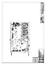
Power Supply
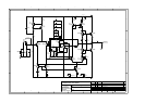
Refer to circuit diagram L896 Sheet 10
The power supply sheet contains the connectors from the power
supply.
SK1003 display supply.
SK1000 Analogue supply.
SK1001 Digital Supplies.
SK1002 Power supply control.
Each of the supplies that is used passes through a LC filter to
reduce any noise in both directions i.e. noise coming in from the
switched mode supply or noise getting out from the noise on the
digital board.
PSU Sync signal
The sync signal is derived from the I2S bit clock (64xFS) signal,
which is divided down by IC1001 and the appropriate output to
sent ( either 96KHz or 88.1 KHz ) to the PSU by the multiplexer
IC1002.
Voltage set and VFD HT shut down
Two resistors set the voltage the Switch mode supply generates
for the display R1008 sets the HT voltage to 36V and R1007 set
the Heater voltage to 5V.
To prevent anode stripping when the heater is switched off the
VFD display has a HT shut down this is performed by Q1000
which shorts the voltage set resistor R1008 to ground.
Regulators
Three regulators are used to provide secondary regulation for
the +/- 15V signal (it is already regulated to +/- 18V on the PSU
PCB) and the 5V analogue supply that is derived from the 18V
regulated supply.
The 2.5V supply for the DSP chips is derived from the 3.3V
supply by using the forward voltage drop of a diode. And a
negative 5V rail is generated using a zenner to provide the bias
voltage for the CMOS switches used in the bass management.
Re-clocking
Refer to circuit diagram L896 Sheet 11
The re-clocking of all of the I2S signals to the DACs is
performed by IC1102 which clocks them all through the d-type
flip flops synchronous to the master clock on pin 9. The Data
signals then go straight to the DACs via series termination
resistors. The Bit clock and word clocks are buffered by IC1100
to provide fan out to the four DACs each with their own series
terminator to reduce reflections.